In this article, we will talk about analog input signals processing in PLC and how can we handle these signals in the automation process.
Contents:
- What are analog input signals?
- Input analog processing in S7-1200 and 1500.
- Input analog processing in S7-300 and 400.
- Which are best for control? – analog or digital signals
- Conclusion.
What are Analog Input Signals?
Before we dive into how to handle analog input signals in TIA Portal, let’s start by understanding analog inputs first.
Any automation system needs input signals to understand the status of the process to be able to take decisions that will keep the process running and stable. These input signals are either discrete or digital input signals which are in the form of 0 or 1 values. The other type of input is the analog signals.
An Analog signal is simply a continuous representation of a physical quantity in your system, so if you need to monitor temperature or pressure in your process, an analog signal will give you continuous and instantaneous values that correspond to the real changes in the physical quantity.
Analog signals are provided in many standard forms, but most commonly the 0-10V or the 4-20mA. It will depend on the type of analog sensor you are using, and it will also dictate the type of PLC analog module that you can use.
Assume an analog pressure sensor that has a measuring range of 0-10 bar and an output in the form of 4-20mA. Usually, an analog signal will have a linear relationship between the measured physical quantity and the corresponding output.
That means if the sensor is measuring a 0 bar it will give a 4mA signal and if it is measuring a 10 bar it will give a 20mA signal and the same in between will also be linear. See picture 1.
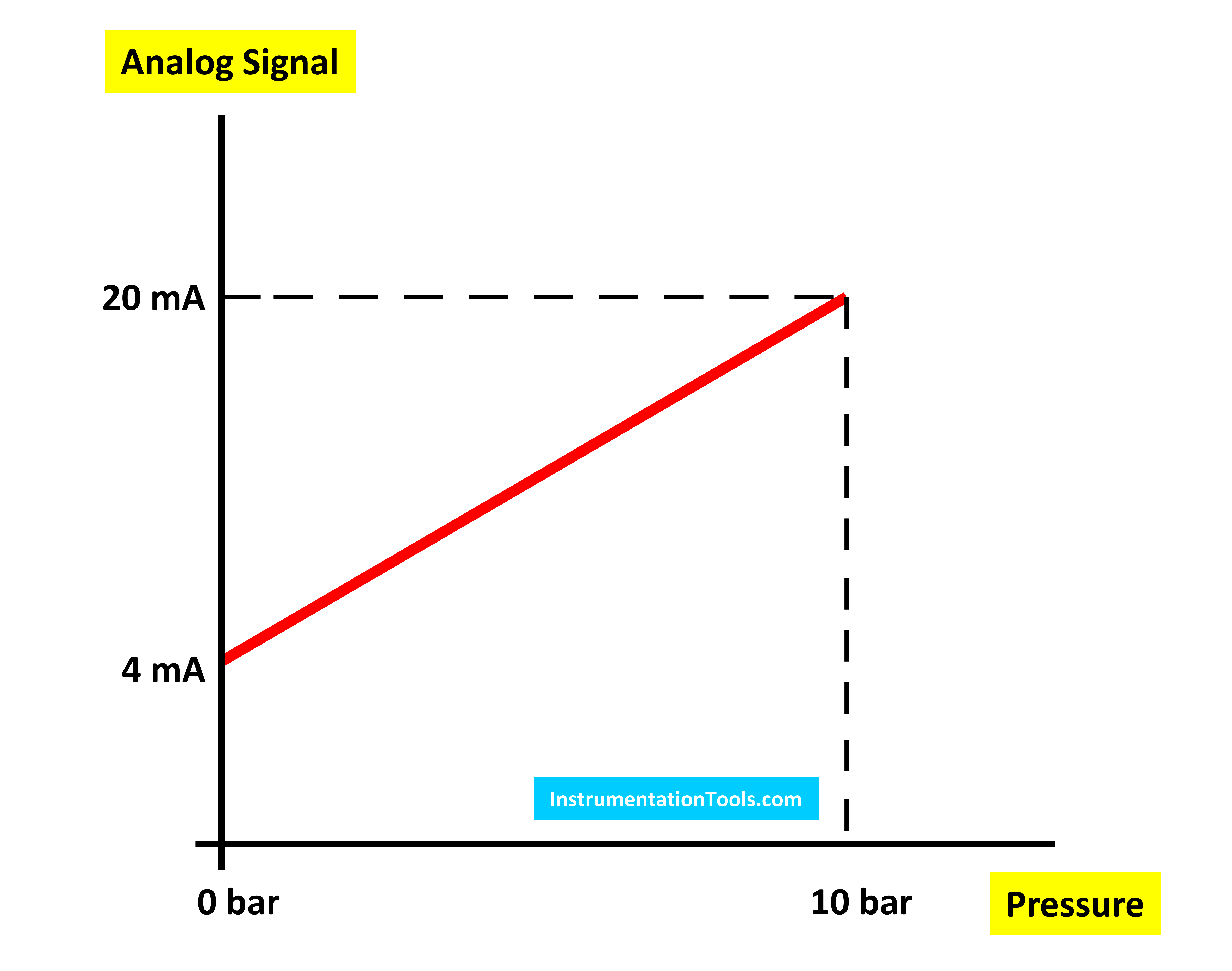
Picture 1 – Analog signal representation.
The PLC still can’t understand the 4-20mA of the physical quantity, and here comes the use of the analog module of the PLC. The analog module will make another transformation to this representation so the PLC can actually understand it.
The analog module will convert the analog mA measurements into digital values that depend on the type of the module, but for Siemens PLC, these values are always in the range of 0 – 27648. So if the sensor is mearing 0 bar the output will be 4mA and it will be converted to 0 value inside the PLC. See picture 2.
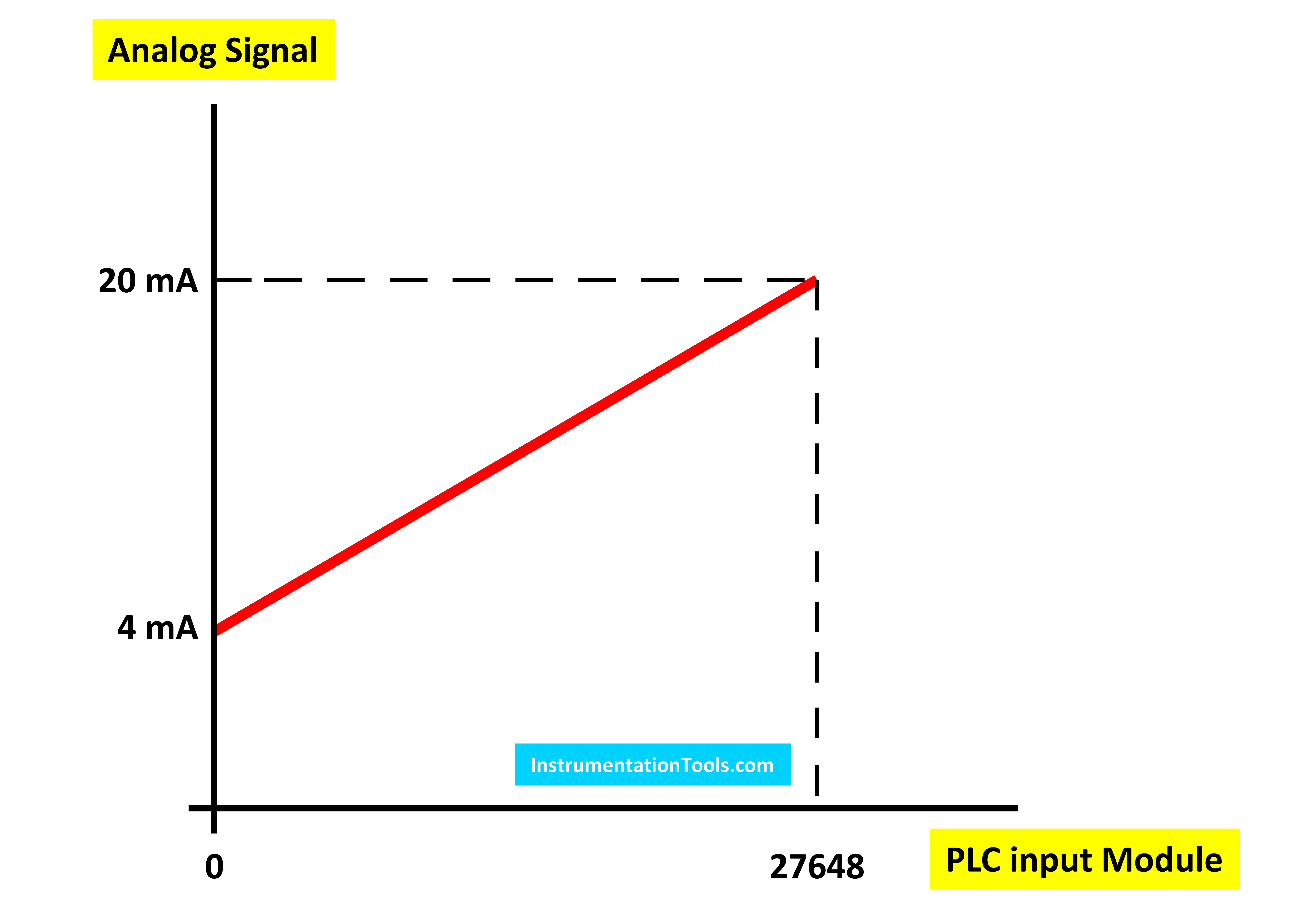
Picture 2 – Analog to digital conversion of the input signal
The PLC will then convert the 0-27648 values into the equivalent physical measurement depending on your programming which we will get to later. See picture 3.
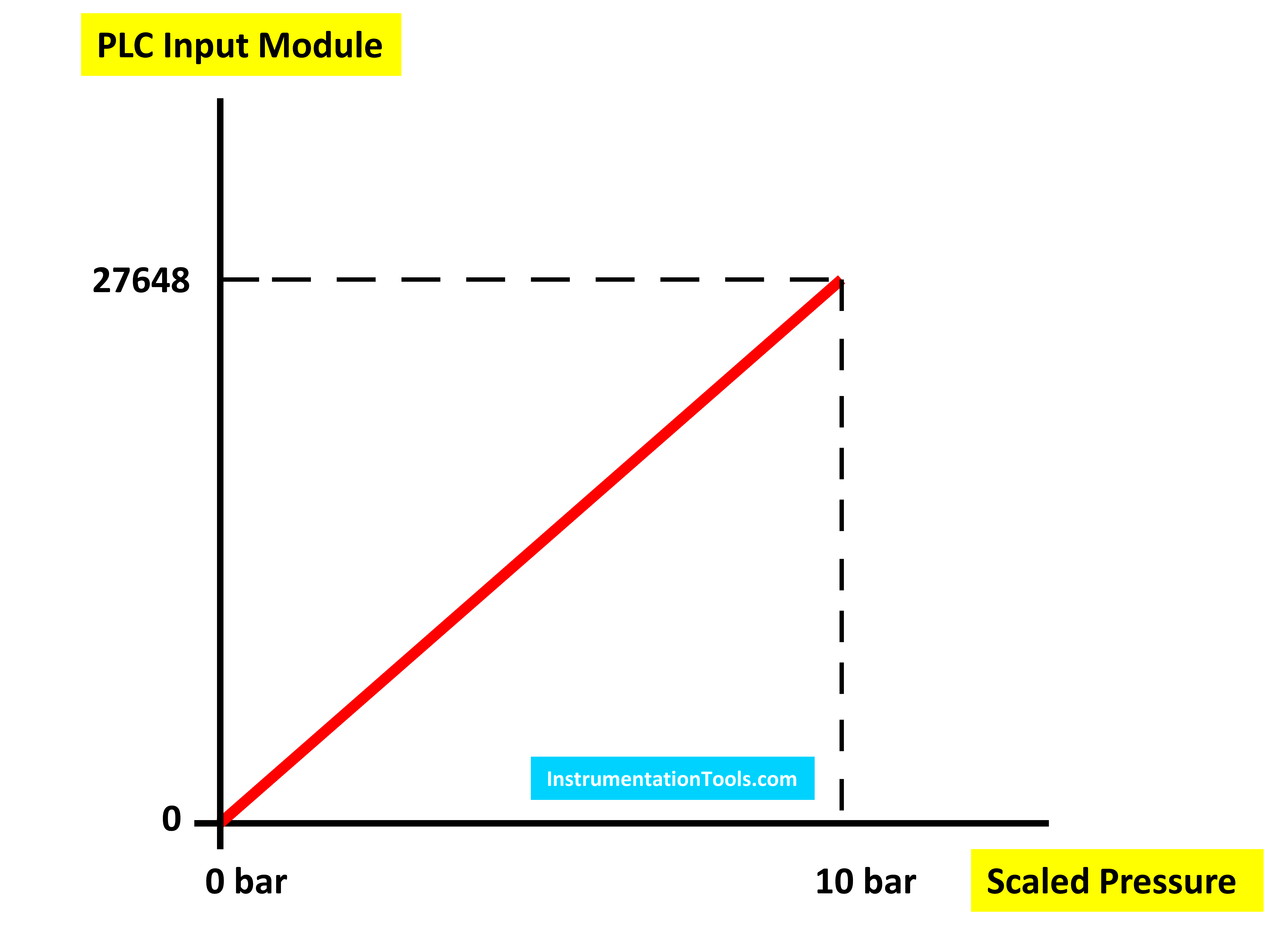
Picture 3 – The scaled measured value inside the PLC.
The analog processing of temperatures is quite different because the temperature sensor behavior with the physical changes is not linear as would a level or a pressure sensor do. That is why there are standardized tables for the different types of temperature sensors that tell which temperature corresponds to which sensor value.
That is why with temperature measurement you would select special types of input modules of your PLC where these standard tables are internally defined and you directly get the temperature value corresponding to the sensor measurement.
That is why you can’t find a temperature sensor that has a voltage or current measurement range written on it. You will only find the sensor type written, for example, PT100, PT1000, KTY84, PTC, and so on.
Analog Input Processing in S7-1200 and 1500
To see how we handle analog signals in modern S7 family PLC, let’s start by creating a new project and adding an S7-1200 CPU. We will also add an analog input/output module. See picture 4.
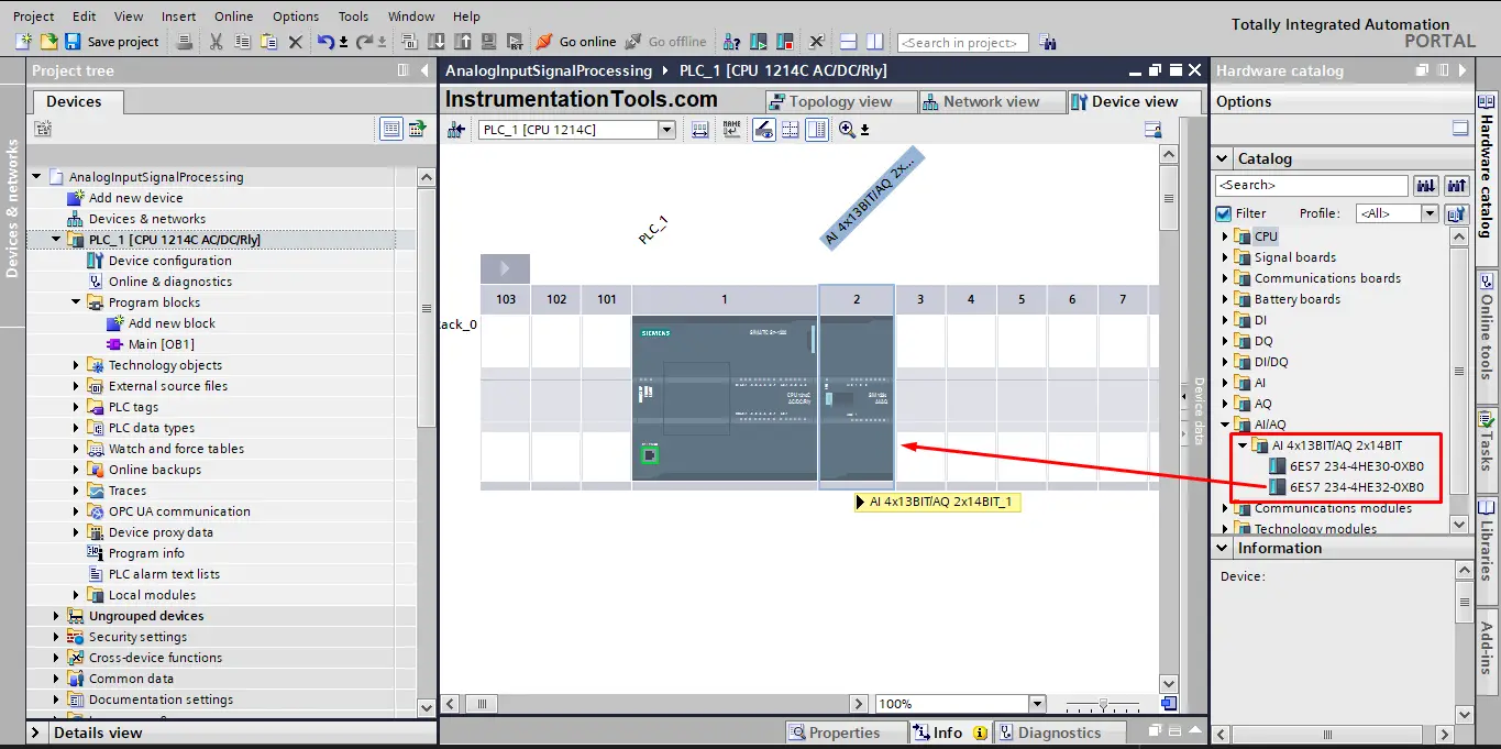
Picture 4 – Adding an analog input module.
Now, let’s define our input signal tag, we will assume a pressure sensor that can measure pressure between 0 and 10 bars and gives a corresponding signal between 4 and 20mA.
We will define that input signal in the first tags of the input module. See picture 5.
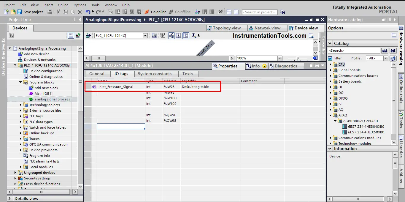
Picture 5 – Define the input signal tag.
As we said before, the input module can work with different input signals, whether it is 0-10V or 4-20mA, so we need to assign the right configuration for our sensor.
As we said the pressure signal is given in the form of 4-20mA so we will configure our input channel to that. See picture 6.
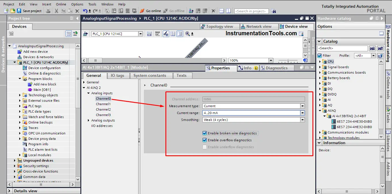
Picture 6 – Configure the input channel
Now that we finished the hardware configuration part, we will start programming our handling code. To do so, we will create a function FC so we can reuse it each time we have an analog signal to process. Inside this FC we will create the logic which will handle the analog signal and convert it into the physical measured value.
In TIA Portal there are predefined instructions that we can use to do just that, these instructions are the NORM_X and the SCALE_X instructions. See picture 7.
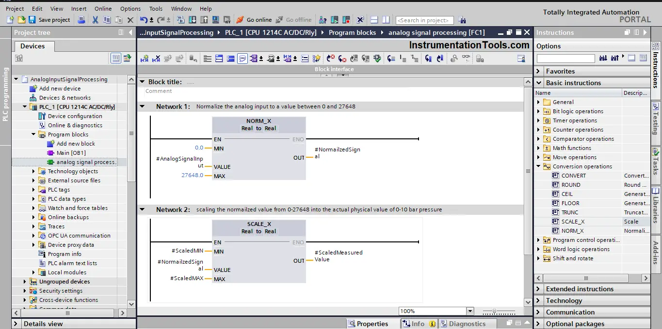
Picture 7 – NORM_X and SCALE_X instructions
As you can see, the NORM_X will normalize the analog input into a value between 0 and 1, and then the SCALE_X will be used to scale this normalized value to the range of the measured physical value, which in our sensor case between 0 and 10 bars.
We used a function FC instead of writing our code directly in the main OB1 to make our code reusable with any analog signal. Each time I have a new analog input signal I will just drag and drop the FC block into our main OB1 and just write the associated parameters of the required input. See picture 8.
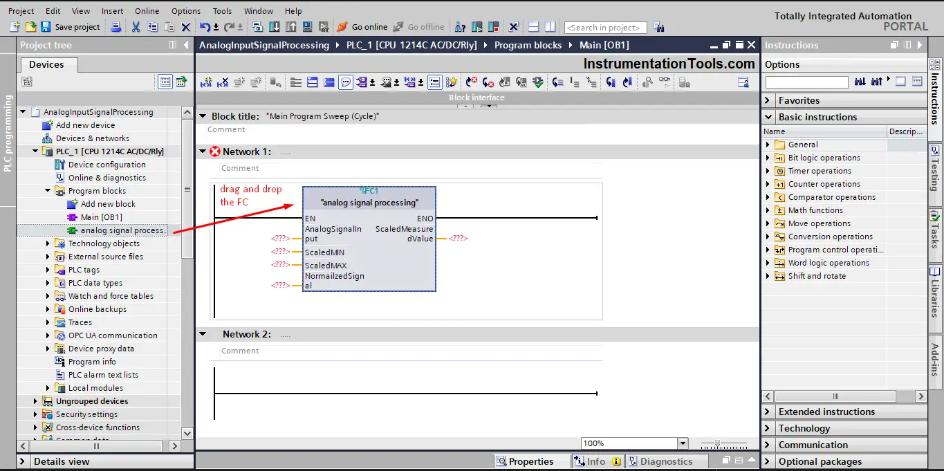
Picture 8 – Drag and drop your FC.
When you drag and drop the FC into your main OB1, you will be asked to provide the associated parameter of this function call.
In our case, the input signal is the pressure sensor and the ScaledMIN and ScaledMAX are the measurement value range of 0-10 bars. See picture 9.
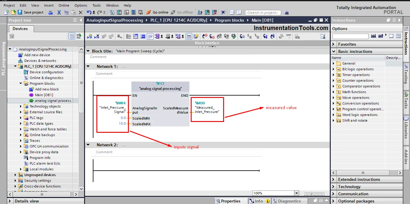
Picture 9 – Assigning the function parameters to our pressure sensor.
If I have a new analog input, then I won’t have to recreate the PLC logic again, I will just drag and drop the FC into the main OB1 and assign the new sensor parameters.
Let’s assume that we now have a new analog sensor for measuring the level inside a water tank between 0 and 100 % of the tank. We will do the same steps as we did before, starting with defining the new input tag. See picture 10.
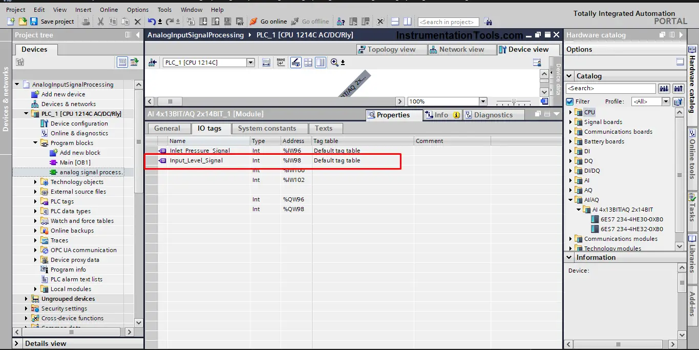
Picture 10 – Define new level sensor
Next, we will configure the input channel for the level sensor as we did in picture 6. We will assume the same configuration.
Next, we will just drag and drop the FC we created and just assign the parameters of the level sensor. See picture 11.
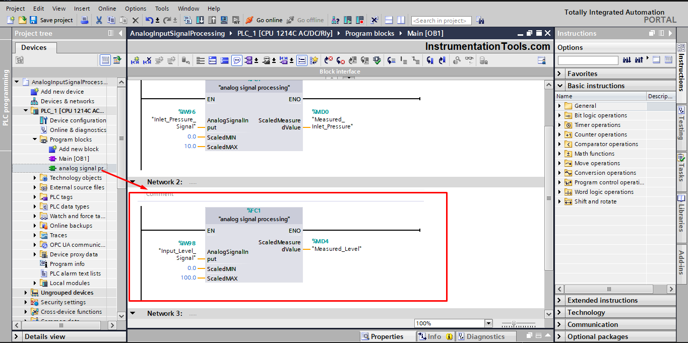
Picture 11 – Reusing the FC with the level sensor.
As you can see from the previous picture, this is one of the many advantages of using functions FCs in your logic as it helped reduce the amount of programming we made.
Now you have a generic code that can be reused many times with any input analog signal you can need in your PLC project.
See the next simulation for input signals processing in Siemens PLC.
Analog Inputs in S7-300 and S7-400
To see how we handle analog signals in older S7 family PLCs like S7-300, let’s start by creating a new project and adding an S7-300 CPU.
The PLC chosen already have enough analog input channels, so we won’t add any analog modules. See picture 12.
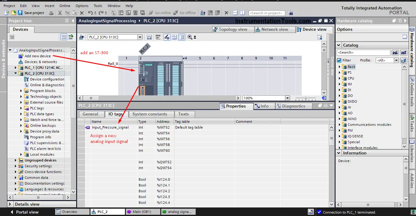
Picture 12 – Add an S7-300 PLC.
Then we will define the new analog sensor tag, we will assume a pressure sensor that has a measuring range between 0 and 100 bar and an output of 4-20mA.
We will configure the PLC input channel as we did before with the S7-1200 to fit our analog input sensor. See picture 13.
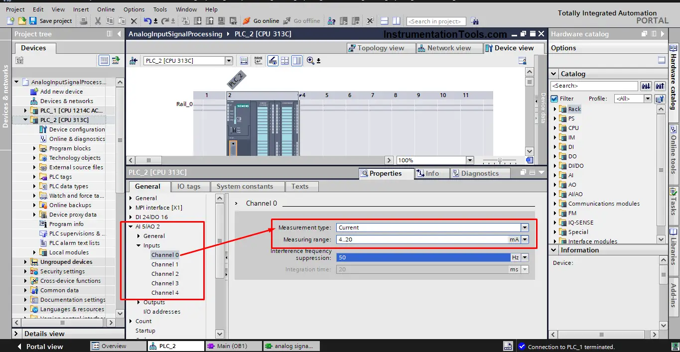
Picture 13 – Configure the input channel.
Now to the PLC coding part, the instruction in s7-300 that is used to handle analog processing is different from the s7-1200.
In the S7-1200 PLCs, we have to use NORM_X and SCALE_X. but with the S7-300 we don’t have the normalized instruction, only a SCALE instruction is used. See picture 14.
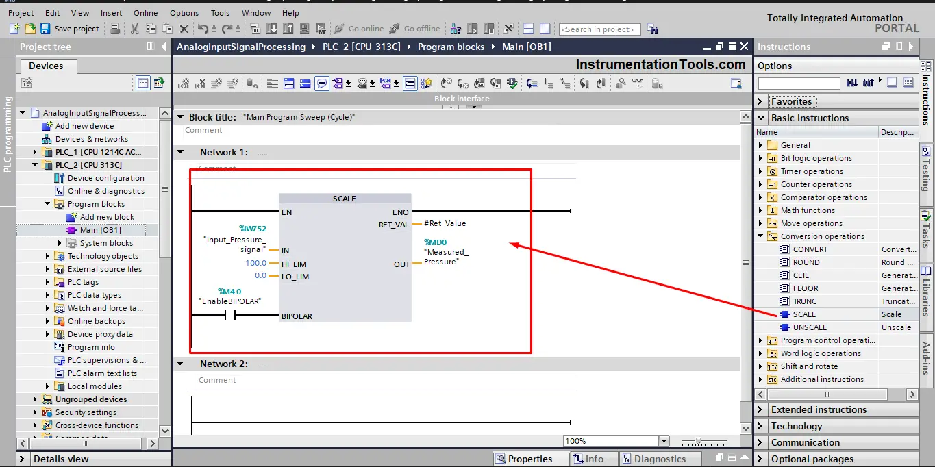
Picture 14 – SCALE instruction in S7-300
As you can see from the previous picture, the SCALE instruction in S7-300 is kind of similar to the NORM_X and SCALE_X instructions combined together. There is one more clear difference which is the BIPOLAR input.
The BIPOLAR input is used to indicate if the value at the IN parameter is to be interpreted as bipolar or unipolar. The parameter can assume the following values:
- BIPOLAR = 1 then the input integer value is assumed to be between -27648 and +27648. For example, when the analog sensor gives us an output in the range of -10V to +10V
- BIPOLAR =0 then the input integer value is assumed to be between 0 and 27648. For example, when the sensor gives us an output in the range of 0-10V
And this is simply how to handle analog input signals in both S7-1200 and S7-300 PLCs.
Downloads:
Which are Best for Control? – Analog or Digital Signals
Look, both signals are critical and useful for any automation system, but I personally prefer to use the analog signals if I can, because having analog signals measurements for the process’s physical quantities will give me continuous monitoring of process parameters which will enable me to better track and control my process.
Also, having continuous monitoring of the parameters will enable me to set different control logic for different signal values, it will make it easier to have a value range for controlling the process and another value ranges for alarms and warnings of the process deviating from normal operation.
Conclusion
- An Analog signal is a continuous representation of a physical quantity in your system.
- Analog inputs are most commonly provided in the 0-10V or 4-20mA range.
- Analog signal processing means converting the analog 4-20mA signal into a range of values that corresponds to the real physical quantity and that the PLC can understand.
- In the modern S7 family of PLCs like S7-1200, handling analog signals is done using the NORM_X and the SCALE_X instructions.
- In the older S7 family of PLCs like S7-300, handling the analog signals is done using the SCALE instruction, which is basically a combination between the NORM_X and the SCALE_X instructions.
If you liked this article, then please subscribe to our YouTube Channel for Instrumentation, Electrical, PLC, and SCADA video tutorials.
You can also follow us on Facebook and Twitter to receive daily updates.
Read Next:
- HMI Screen Design Applications
- Static and Temp Variables in PLC
- Power Supply Sizing for Systems
- How to Read the PLC Datasheet?
- Firmware Version of a PLC System