Inst ToolsInst ToolsInst Tools
  • Courses
  • Videos
  • Q & A
    • Interview
      • Instrumentation
      • Electronics
      • Electrical
      • Practical Questions
    • MCQ
      • Instrumentation MCQ
      • Electrical MCQ
      • Electronics MCQ
      • Control Systems MCQ
      • Analog Electronics MCQ
      • Digital Electronics MCQ
      • Power Electronics MCQ
      • Microprocessor MCQ
      • Multiple Choice Questions
  • EE
    • Electronics
      • Electronics Q & A
      • Electronic Basics
      • Electronic Devices & Circuits
      • Electronics Animation
      • Digital Electronics
    • Electrical
      • Electrical Basics
      • Electrical Q & A
      • Power Electronics
      • Electrical Machines
      • Electrical Animation
      • Power Systems
      • Switchgear & Protection
      • Transmission & Distribution
  • Measure
    • Control Valves
    • Calibration
    • Temperature
    • Pressure
    • Flow
    • Level
    • Analyzers
    • Switches
    • Vibration
    • Solenoid Valve
  • Control
    • PLC Tutorials
    • Control Systems
    • Safety Instrumented System (SIS)
    • Communication
    • Fire & Gas System
  • More
    • Design
    • Tools
    • Animation
    • Basics
    • Formulas
    • Standards
    • TextBooks
    • Common
    • Software
    • Excel Tools
    • Erection & Commissioning
    • Process Fundamentals
    • Videos
    • Books
Search
All rights reserved. Reproduction in whole or in part without written permission is prohibited.
Reading: Extended Timer Logic in PLC
Share
Notification Show More
Font ResizerAa
Inst ToolsInst Tools
Font ResizerAa
  • Courses
  • PLC Tutorials
  • Control Systems
Search
  • Courses
  • Videos
  • Q & A
    • Interview
    • MCQ
  • EE
    • Electronics
    • Electrical
  • Measure
    • Control Valves
    • Calibration
    • Temperature
    • Pressure
    • Flow
    • Level
    • Analyzers
    • Switches
    • Vibration
    • Solenoid Valve
  • Control
    • PLC Tutorials
    • Control Systems
    • Safety Instrumented System (SIS)
    • Communication
    • Fire & Gas System
  • More
    • Design
    • Tools
    • Animation
    • Basics
    • Formulas
    • Standards
    • TextBooks
    • Common
    • Software
    • Excel Tools
    • Erection & Commissioning
    • Process Fundamentals
    • Videos
    • Books
Follow US
All rights reserved. Reproduction in whole or in part without written permission is prohibited.
Inst Tools > Blog > PLC Tutorials > Extended Timer Logic in PLC

Extended Timer Logic in PLC

Last updated: March 4, 2021 12:39 pm
Editorial Staff
PLC Tutorials
2 Comments
Share
5 Min Read
SHARE

Extended Timer logic using Timer and Counter in PLC

Contents
Inputs and OutputsExtended Timer Logic in PLCLogic Description

In process industries where we deal with many processes in which some of the processes run based on the timer. Some require less time to run and other processes require a longer time.

Processes with smaller timing don’t have an issue but, the processes which require longer times have the issue, especially with Siemens PLCs. The default Siemens PLC timers capable of maximum timing is 2 hours 46 minutes.

If we need more timing functionality in our complex process control logic then we have to create a custom timer block that will handle higher timings than the default system provided value.

In this article, we will be discussing the extensive timer logic using the PLC program.

Let’s consider an example of a pump that needs to run for four straight hours. We will be using two inputs and a pump as an output.

Inputs and Outputs

Inputs: 1. START (I0.0), 2. STOP (I0.1)

Output: 1. PUMP (Q0.0)

Timer: TO

Counter: C0

Extended Timer Logic in PLC

We are using here a timer and counter to run the pump for four straight hours. For this, we need a timer to run for 2 hours and a counter to count up to 2 times. Here timer provides the timing value and counter provides the number of times the timer has to run. So, 2 hours x 2 times = 4 hours.

If we need more timing hours means we have to simply change the value of the timer and counter respectively.
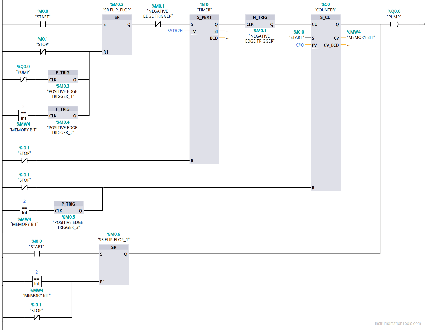
Extended Timer Logic in PLC

Logic Description

When the START button is pressed, which will set the SR flip-flop output then the signal will pass through a timer (S_PEXT). This timer will stay active for a time interval defined by the user.

After timer, a negative edge trigger is used (N_TRIG) which will only energize when the timer goes from true state to false.

The timer stops timing, due to the negative edge gets triggered the counter will energize and the pump will ON till 2 hours as we have selected 2 hours in the timer. (in timer’s first iteration).

We have used NC contact of N_TRIG in between flip-flop and timer. When the counter counts 1 and timer start again timing and will continue for another 2 hours, that makes 4 hours of pump run.

When timer finished timing due to the negative edge it will energize counter again and will count 2.

Now as you can see in the reset of a flip-flop, the comparator is used which is set to 2 and compare it with counter’s cv value MW2. So, when the counter reaches 2 it will activate compare instruction which then passes through the P_TRIG which only allows the signal to pass only once in a cycle.

Now in the same way with NC contact of the pump is used because when timer logic completes it’s 4 hours of counting, the pump will get off and due to NC contact, it will reset SR flip-flop.

For the reset of the counter, the same concept is used. When the counter reaches counts of 2 then signal pass through P_TRIG and reset the counter.

In the last rung, a START button added with SR flip-flop so when you press START button it will set the pump and timer also start timing with it. After 4 hours the pump automatically de-energize due to the compare instruction which will compare with the counter, in our case it is 2.

STOP button is used to stop the whole process.

Author: Suhel Patel

If you liked this article, then please subscribe to our YouTube Channel for PLC and SCADA video tutorials.

You can also follow us on Facebook and Twitter to receive daily updates.

Read Next:

  • Troubleshoot PLC Program
  • Lube Oil Pump Logic
  • PLC Maths Instructions
  • Pulse Generation using Timer
  • Liquid Mixing PLC Logic
Don't Miss Our Updates
Be the first to get exclusive content straight to your email.
We promise not to spam you. You can unsubscribe at any time.
Invalid email address
You've successfully subscribed !

Continue Reading

4-20 mA Transmitter Wiring Types : 2-Wire, 3-Wire, 4-Wire
PLC Emergency Stop Example Program
VFD Simulator Download – Free Yaskawa V1000 Software
Schneider PLC Example: Control Lamps Sequences
Product Painting PLC Program using Omron CX-Programmer
Smart Spray System using Wecon PLC
Share This Article
Facebook Whatsapp Whatsapp LinkedIn Copy Link
Share
2 Comments
  • Nani says:
    April 9, 2020 at 12:25 pm

    Hello,

    I don’t understand you. Explain clearly. Its all confusing.

    Reply
  • Suhel patel says:
    April 9, 2020 at 12:59 pm

    Hello
    Yes because it bit lengthy and you have read properly and follow each rung with program description. Try this program in your software and then read description properly. I hope you will get it then.

    In order to understand it properly you have to write this program in your software and follow it, otherwise by only reading the logic doesn’t make you understand it.

    Reply

Leave a Reply Cancel reply

Your email address will not be published. Required fields are marked *

Stay Connected

128.3kFollowersLike
69.1kFollowersFollow
208kSubscribersSubscribe
38kFollowersFollow

Categories

Explore More

Introducing PLC Programming using LogixPro Simulator Software
How to Detect Speed of Conveyor in PLC?
Troubleshooting PLC Permissive Inputs
What is Interposing Relay in a PLC System ?
Basic PLC Ladder Programming Example
Studio 5000: Define Program or Operator Control in Functional Block Diagram
Why different PLC Programming Languages were Developed?
PLC Program for Positive Edge Pulse Output for One Scan Cycle

Keep Learning

Liquid Tank Filling and Emptying PLC System

Auto and Manual Liquid Tank System: PLC Program Example

SR Flip Flop Logic

How to implement SR Flip Flop using PLC Ladder Logic

Midline output instruction

What is Midline Instruction in Siemens PLC?

Programmable Logic Controller Quiz

Programmable Logic Controller Quiz

Siemens S7 300 and STEP 7 PLC program using SIMATIC Software

Masking in PLC

What is Masking in PLC?

Mixing Process with Valve Control

PLC Mixing Process with Adjustable Timer and Valve Control

Energy Meter Data in PLC using Modbus Communication

Modbus Communication between PLC and Energy Meter

Learn More

Digital Input and Output Devices Objective Questions

Digital Input Output Devices Objective Questions

PID Controller Graph - 3

PID Controllers Graphical Analysis

Comparison of Level Meters - Level Measurement Instruments

Comparison of Level Meters – Level Measurement Instruments

How Nuclear Radiation is used to Measure Coke Dust Level?

How Nuclear Radiation is used to Measure Coke Dust Level?

Liquid Nitrogen in Instrumentation

Liquid Nitrogen in Instrumentation

PLC Cooking Timer Example for Kitchen Automation

PLC Cooking Timer Example for Kitchen Automation

OPC Server

What is the OPC Server?

old Pressure Switches

Pressure Switch Frozen Screwed Cover Extends the Plant Shutdown

Follow US
All rights reserved. Reproduction in whole or in part without written permission is prohibited.
Welcome Back!

Sign in to your account

Username or Email Address
Password

Lost your password?