Design a PLC Program for automatic mixing control in a tank. This is the best example to learn PLC programming.
Automatic Mixing Control in a Tank
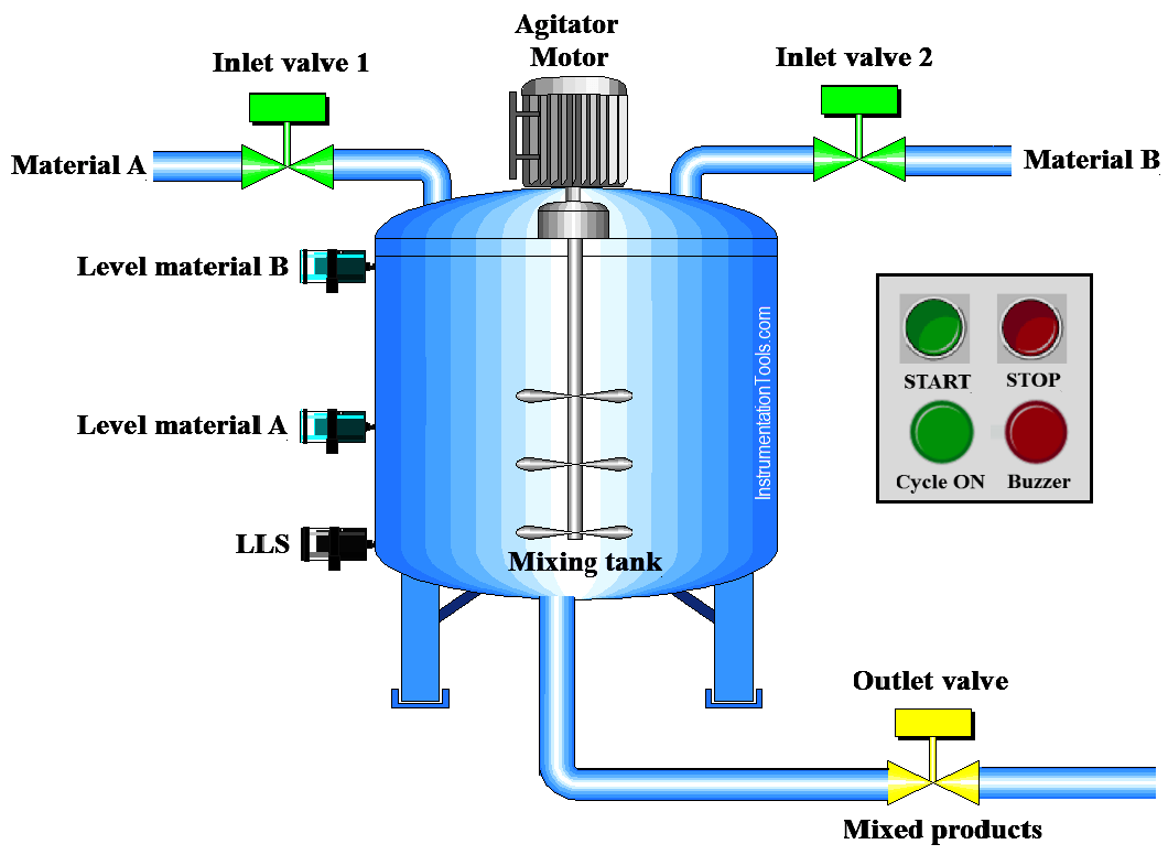
Material A and material B are collected in a tank. These materials will be mixed for a particular time and then the mixed product drained out through the outlet valve.
Implement a ladder program for this application in PLC.
Problem Diagram
Problem Solution
In this example, we use PLC programming of Siemens S7-300 PLC. We can use other PLC also for this application.
Two level sensors are used for detecting the level of material A and material B. Also one bottom level sensor used for detecting the bottom level.
To control level of this system, single acting valve is used which has two states, either fully opened or fully closed.
Particular is provided to mix the material A and material B in a tank. We can use on delay timer this function.
After successfully completion of mixing, outlet valve is operated to drain the mixed material.
When mixing process is completed, buzzer will be activated and it will remain ON and after 5sec it will be automatically OFF.
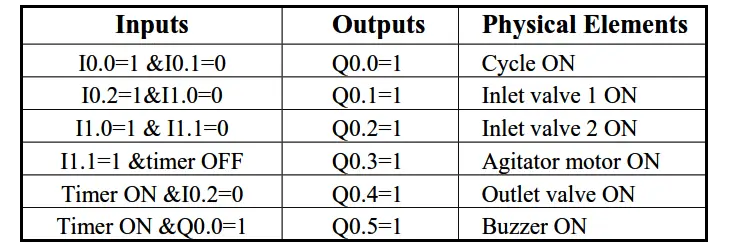
List of inputs/outputs
Digital Inputs
- Cycle START :- I0.0
- Cycle STOP :- I0.1
- Low level switch :- I0.2
- Level material A :- I1.0
- Level material B :- I1.1
Digital outputs
- Cycle ON :- Q0.0
- Inlet valve 1 :- Q0.1
- Inlet valve 2 :- Q0.2
- Agitator motor :- Q0.3
- Outlet valve :- Q0.4
- Buzzer :- Q0.5
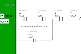
PLC Logic for Automatic mixing control in a tank
PLC Logic Explained
For this application, we used S7-300 PLC and TIA portal software for programming.
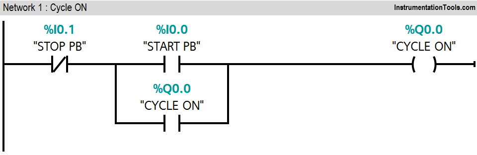
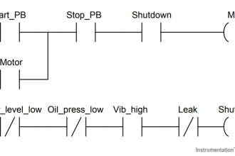
Network 1:
In network 1 latching circuit is used for latching the cycle. When START PB (I0.0) is pressed, cycle ON (Q0.0) output will be ON and it can be STOP by pressing STOP PB (I0.1).
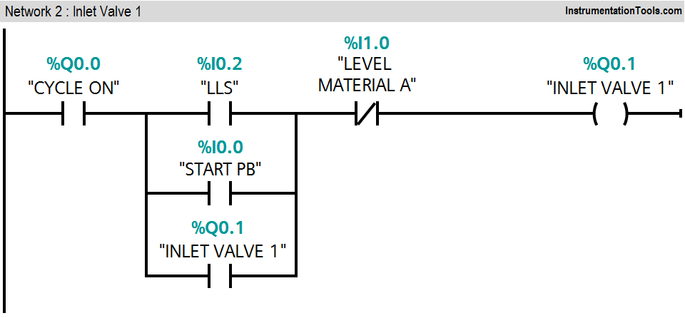
Network 2:
When the bottom level switch (I0.2) is detected and level material A (I1.0) is not detected, inlet valve 1 will be ON (Q0.1).
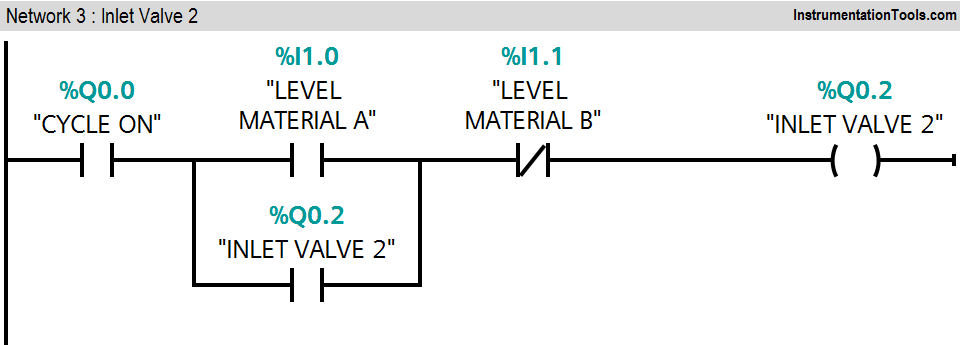
Network 3:
When level material A (I1.0) is detected and level material B (I01.1) is not detected, inlet valve 1 will be ON (Q0.1).
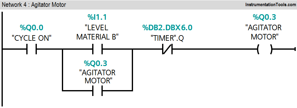
Network 4:
When the tank is full of material A and material B, level material B s detected. This detection energizes the agitator motor and we need mixing for 20 s, so timer instruction will be ON with agitator motor (Q0.3).
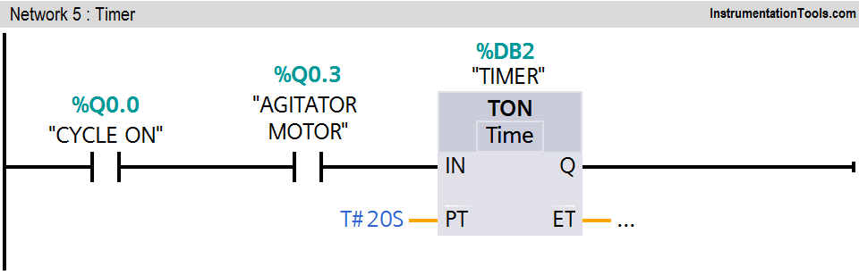
Network 5:
Timer instruction will be executed when agitator motor (Q0.3) is activated.
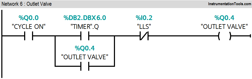
Network 6:
When mixing process is completed, Outlet valve (Q0.4) will be ON for draining the mixed material.
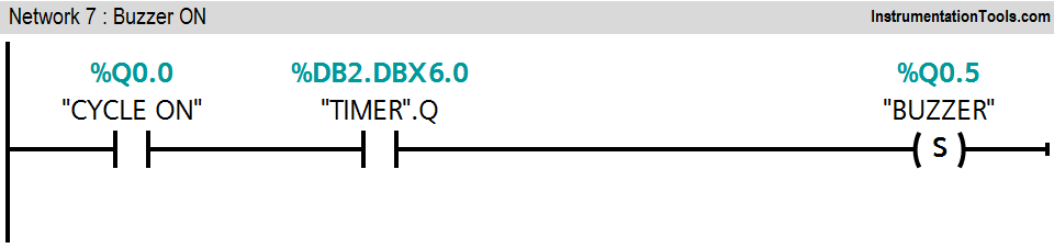
Network 7:
When mixing process completed successfully, buzzer (alarm) will be ON (Q0.5).
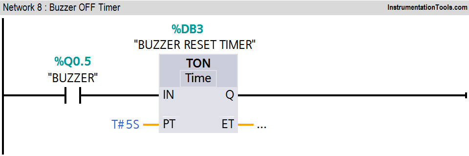
Network 8:
Buzzer will remain ON for 5 second after 5sec it will be OFF. Here timer instruction is executed.
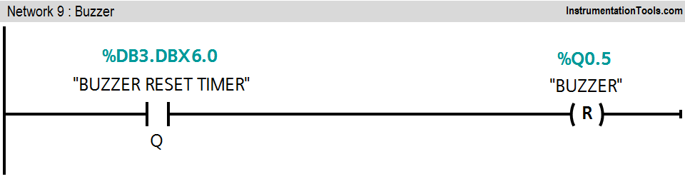
Network 9:
When Buzzer ON delay completed, buzzer output will be OFF automatically.
Note:- Above application may be different from actual application. This example is only for explanation purpose only. We can implement this logic in other PLC also. All parameters are considered here for explanation.
Result
Author: Bhavesh
If you liked this article, then please subscribe to our YouTube Channel for PLC and SCADA video tutorials.
You can also follow us on Facebook and Twitter to receive daily updates.
Read Next:
- PLC Level Control of Parallel Tanks
- Control Valves Application using PLC
- PLC Tank Heating Control using Heater
- 1 to 8 Demultiplexer PLC ladder diagram


Its very educative to engineering sector,thanks very much
There is a problem in network 3, it should be locked with the outlet valve also. As once draining process start network 3 will energize again and start filling the tank up to level 2
This is very informative. Can you please make similar program for analog inputs?
Good informations