In previous articles, we discussed what an organization block is, and we talked about the main cyclic interrupt OB1 and the time of day interrupt OB10.
In this article, we will continue discussing the different OBs, and this time we are talking about the Time Delay Interrupt organization block or OB20.
Contents:
- What is OB20?
- How to call OB20?
- Parameters of SRT_DINT instruction.
- Example Program.
- Conclusion.
What is Time Delay Interrupt (OB20)?
OB20 is an organization block that is called and executed by the operating system, but we have to tell the operating system when to call this OB20.
The operating system gets the information from the user PLC program to call this OB20, it will wait for the delay time configured then it will call and execute whatever logic is inside the OB20.
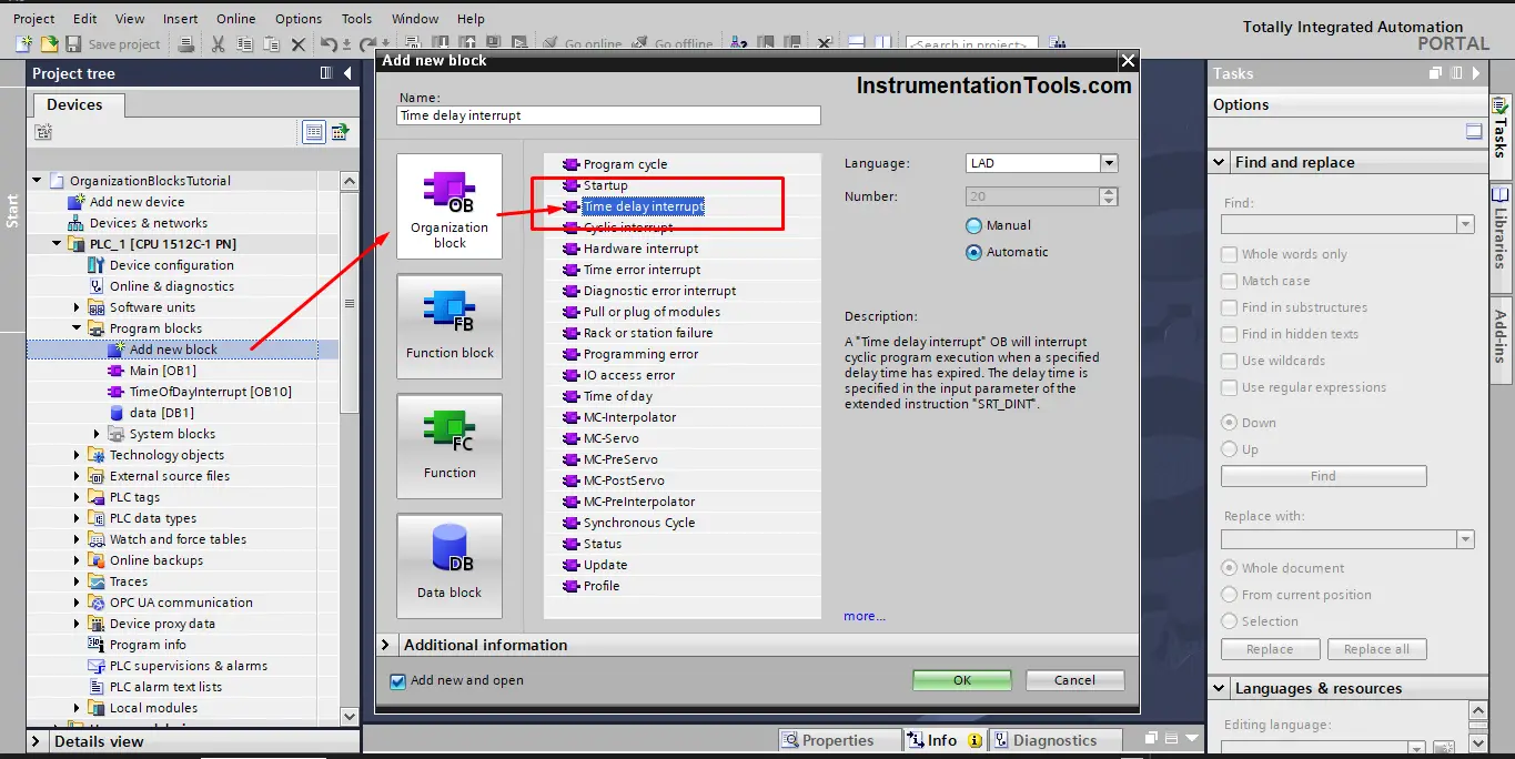
We create an OB20 block from Add a new block in the project tree. See picture 1.
Now that I have created a time delay interrupt, when will it be executed? And how to configure the time delay of the block execution?
Again, OB20 is an organization block, which means you don’t call the block to be executed, but you tell the operating system when it can call it and execute whatever functionality is written inside.
How to Tell the Operating System to Call the OB20?
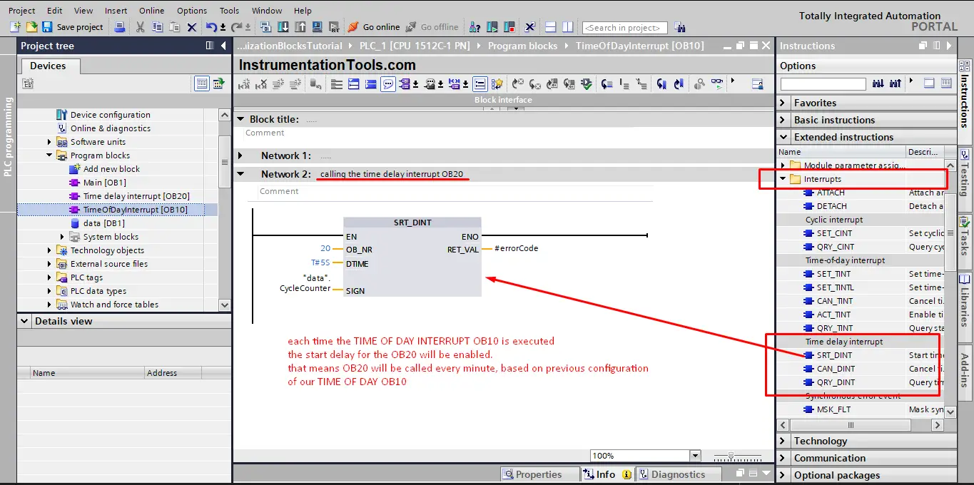
To tell the operating system that we want to call the OB20, we use the SRT_DINT or start time delay interrupt, see picture 2.
Parameters of SRT_DINT instruction
As you see from the last picture, you can use the SRT_DINT instruction to call the OB20. but you need to configure some parameters, for the instruction to work.
EN: the instruction will not be executed until a negative edge signal is presented at the EN input. That means you have to assign a condition of the set of conditions to enable signal and the instruction will only work when this condition is true then false again.
OB_NR: you assign the number of the delay interrupt that you need to call, in our case 20 as we created OB20, but we can create more than one delay interrupt and then we will have to call each one with a separate SRT_DINT instruction.
DTIME: that is the delay time you want to wait before executing the OB20, we will set this time to 5 seconds for the sake of simulation.
SIGN: Identifier that appears when the time-delay interrupt OB is called in the start event information of the OB.
Example PLC Program
To better understand the OB20, we will create a simple logic to see how an OB20 can be called and executed. We will build this PLC example on the previous logic we made for the OB1 and OB10 in previous articles.
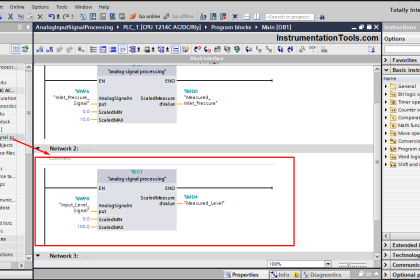
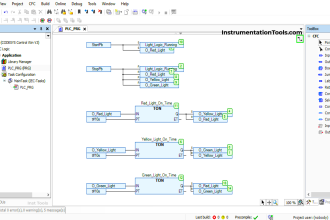
Inside the OB20 we will create a logic that counts how many OB1 cycles have been called and executed within the 5 seconds delay time that we have configured for the OB20. See picture 3.
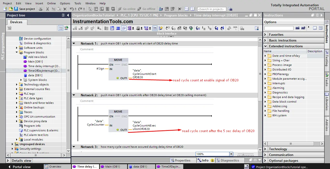
In the last picture, you see that we used MOVE instruction to push information on cycle counts at the start of the OB20 call and after it has been executed.
See picture 4 for the rest of the logic.
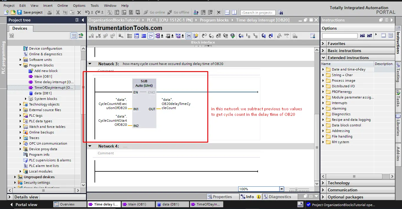
After that, we will subtract the two values of cycle counts to get how many cycles have been executed within the five seconds delay.
Now that we have created the logic we want, how can we call the OB20? As explained before we have to use the SRT_DINT instruction. We will use this instruction inside the OB10 which we have configured before to be executed every minute. That means the OB20 will also be called and executed every minute but with a delay time of 5 seconds.
In the previous article we built a logic that calls how many times the OB1 is being called and executed, we also built another logic that will call the OB10 every minute.
In this example, we will use the call of the OB10 to call the OB20. See picture 5.
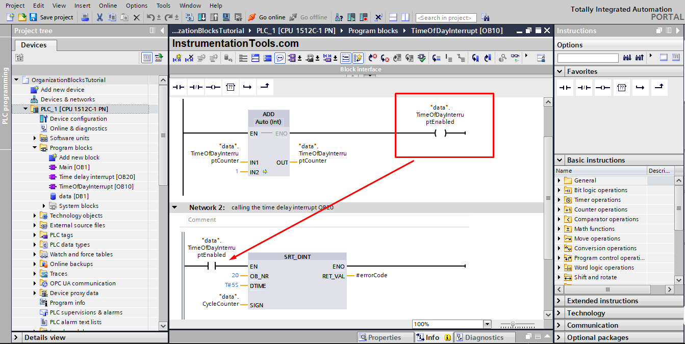
We said before that the SRT_DINT needs a negative edge signal at the EN for the call to start. That is why we used the TimeOfDayInterruptEnabled signal which we know it will be true when OB10 is executed and then go back to false giving us the edge signal we need.
Now that all PLC logic is complete, let’s compile and run a new simulation. See the following simulation of our project.
You see in the animation at first the values of cycle counts are zeros but when the OB10 is called and the TimeOfDayInterruptEnabled is true logic will wait 5 seconds then the count values will be updated with cycle counts.
Downloads:
Conclusion
- OB20 is an organization block called and executed by the operating system.
- We can tell the operating system to call the OB20 with the SRT_DINT instruction.
If you liked this article, then please subscribe to our YouTube Channel for Instrumentation, Electrical, PLC, and SCADA video tutorials.
You can also follow us on Facebook and Twitter to receive daily updates.
Read Next:
- Global Data Blocks in PLC
- Configure the Time in PLC
- SCADA System Architecture
- Difference between PLC and HMI
- HMI and VFD Control with Modbus


I love instrumentationtools.com