Question 1: A waste heat recovery boiler main steam line flow transmitter (DPT type) (range 0 to 10000 mmWC) at temperature 515° C. How to convert mm WC into tone per hour mass flow rate unit?
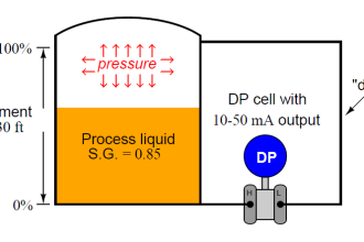
Question 2: Can I use the same transmitter for level measurement?
Basics
To understand the answer to the first question readers must know the below-given orifice, venturi, flow nozzle, etc.
Sizing information. Orifice, and other restriction devices flow formula is
Q = 0.01252cdd2h0.5/((1-m2)γ)0. 5 for liquids Equation 1 (E1)
Q = 0.01252cdd2εZh0.5/((1-m2)γ0.5) for gases Equation 2 (E2)
W = 0.01252cdd2εZ h0.5 /((1-m2)γ0.5) for steam and vapors Equation 3 (E3)
Where:
Dh for a circular pipe = 4*0.25πd2/πd = d the pipe ID
Dh for a square duct of side a = 4a2/4a = a
Dh for arectangular duct of sides a and b = 2ab/(a+b)
| # | Symbol | Explanation | Units |
| 1 | Q | Flowing conditions Liquid/gas flow rate | m3/H |
| 2 | W | Flowing conditions Steam / Vapors flow rate | kg/H |
| 3 | 0.01252 | SI units Constant | |
| 4 | cd | Discharge Coeff | None |
| 5 | d | Orifice / venturi / flow nozzle throat dia | mm |
| 6 | D | Pipe bore dia | mm |
| 7 | ε | Expansion Factor | None |
| 8 | Z | Gas Compressibility Factor | None |
| 9 | m | Restriction area / pipe bore area ratio (d/D)2 | None |
| 10 | γ | Liquid / Gas density at flowing conditions | Kg/m3 |
| 11 | v | Steam flowing conditions specific volume from steam tables or online steam calculator | m3/kg |
Formulas Symbols Explanation
Discharge Coefficient Cd
Actual flow rates are always lower than the theoretical formulas calculated flow rates. Cd, the discharge coefficient corrects this error.
Most industrial flows are turbulent flows. The Cd values apply to these, subject to minor corrections where a flow characteristic called Reynolds Number is < 25*105.
Calculating Flows through non-circular pipes
Scientists recommend using the section’s Hydraulic Diameter Dh:
Dh = 4As/P
Where:
Dh – The section’s hydraulic diameter m
AS – The section’s wetted Area m2
C – The section’s wetted perimeter length m
According to this formula:
Dh for a circular pipe = 4*0.25πd2/πd = d the pipe ID
Dh for a square duct of side a = 4a2/4a = a
Dh for a rectangular duct of sides a and b = 2ab/(a+b)
Reynolds Number
Reynolds Number is a very important quantity for studying fluid flow patterns. It is fluid mechanics widely used as a dimensionless parameter.
A flowing fluid’s Reynolds Number definition is the flowing fluids’ inertia force to the viscous force ratio; it quantifies these two types of forces the relative importance for given flow conditions.
The British scientist George Stokes introduced Reynold’s number concept in 1851. However, the British physicist Osborne Reynolds popularized its use in 1883; hence, it got the name Reynolds Number.
The Reynolds number depends on the relative internal movement due to a flowing fluid stream’s different fluid velocity, hence it is fluid flow analysis, a pre-requisite.
The flowing fluid has relative internal movements due to different fluid velocities. Reynolds number is within a fluid inertial to viscous forces ratio.
A region where these forces change behavior is known as a boundary layer, such as the bounding surface in the interior of a pipe. This relative movement generates fluid friction, contributing to turbulent flow development.
The fluid viscosity opposes this effect and tends to prevent turbulence. The Reynolds number quantifies the inertial and viscous forces’ relative importance for given flow conditions and helps determine whether the flow is laminar or turbulent.
Turbulent flow onset predicting ability is a design tool for piping systems, aircraft wings, fluid dynamics problems scaling up.
Scientists use the Reynolds number in scaling experimental laboratory models of fluid flows behavior to large-scale industrial flows. E.g., a model airplane’s flight behavior study in a lab wind tunnel given Re air velocities helps designing passengers and other aircraft.
In addition, Re extends using lab models studies determined fluid flow behavior information in large industrial pipeline flows. Often such scaling is nonlinear, yet Re application to both situations enables developing scaling factors.
At low < 2100 Re, the viscous forces keep the fluid particles in line making the flow smooth and constant aka laminar flow.
At large Re > 4000 flows starts to produce chaotic eddies, vortices, and other flow instabilities making the flow turbulent. The more is the Re the higher is the more turbulent the flow. Most industrial flows are > 25*105 Re flows.
Below is the formula to calculate Reynolds Number (Re):
Re = uL/ν =γuL/μ
| # | Sym | Explanation | Unit |
| 1 | Re | Reynolds Number | None |
| 2 | u | Flowing stream velocity | m/s |
| 3 | γ | The fluid density | Kg/m3 |
| 4 | L | Length scale that characterizes the scale of the flow motions of interest. For pipe’s ducts L= Dh the hydraulic diameter | m |
| 5 | μ | The fluid dynamic viscosity | Pa·s, or N·s/m2, or kg/(m·s)) |
| 6 | ν | The fluid kinematic viscosity | (m2/s). |
ISO 5167 Orifice Plate
ISO 5167 1991 offers flowmeter orifice plates three versions, a method to calculate cd the discharge coefficient for different ‘m’ ratios.
The flow measuring orifice is just a circular plate with a machined opening for fluid flows.
Pressure Tap Locations
1991 ISO 5167 standards covered flowmeter orifices three standard pressure taps are:
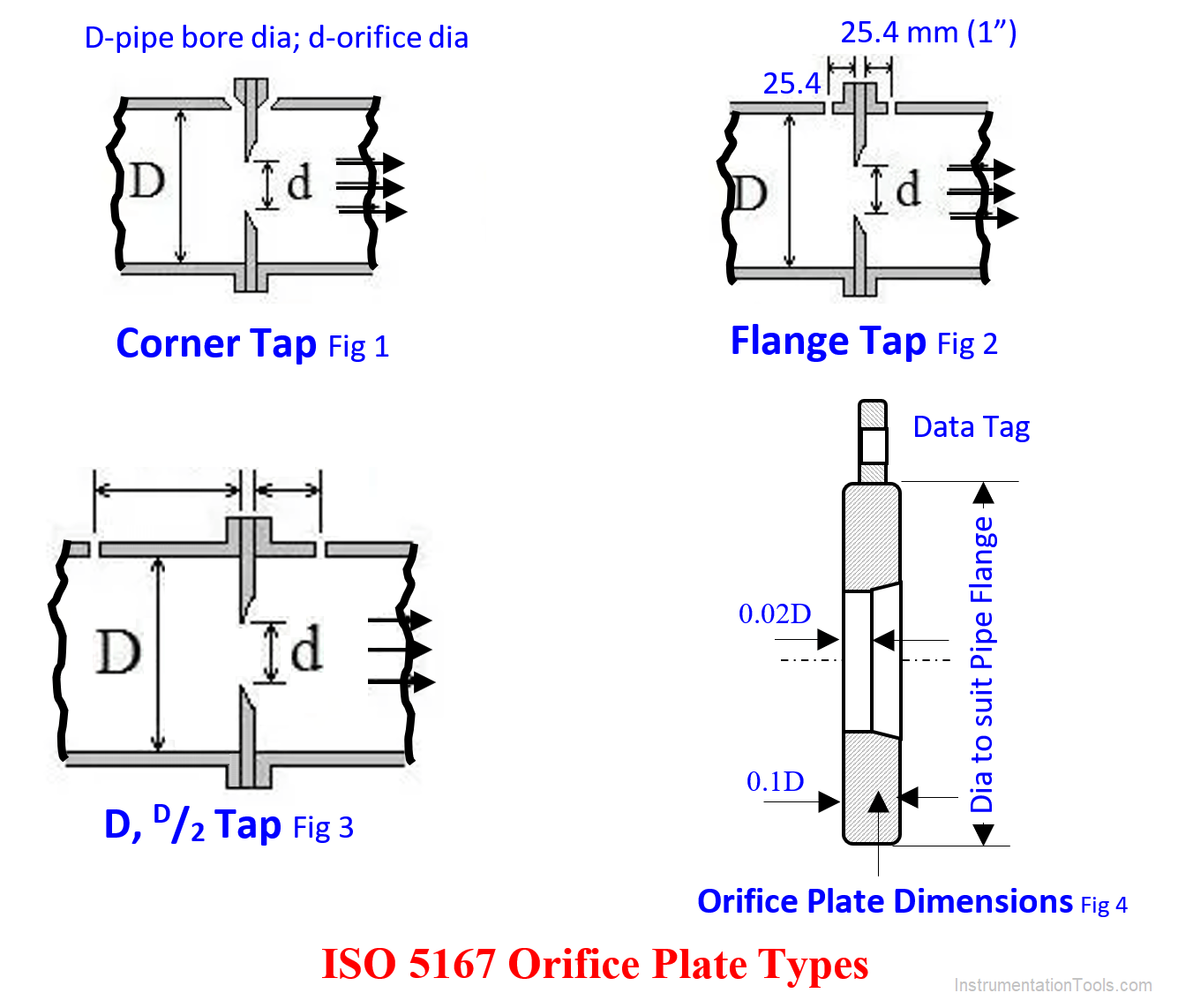
The Corner Taps
The corner taps (Fig 1): The upstream tap outer extremity distance from orifice upstream side ≤0.03 D; D-pipe bore dia; The downstream tap outer extremity distance from orifice upstream side ≤0.13D; Orifice plate thickness ≤0.1 D (fig 4).
The orifice bore cylindrical distance ≤0.02D; Where because of pressure considerations orifice thickness exceeds 0.02D, taper off the excess portions; max included angle 45O.
Flange Taps
The flange taps (fig 2): The upstream and downstream tap CL from Orifice plate edges = 25.4 mm (1”); The tap opening at the pipe wall = D/16 subject to max 12.7 mm. Beyond that to suit the connecting fittings.
I have seen an instrument engineer trying to clear a choked 2” Natural gas pipe Orifice Tap with an 8-mm dia rod he found nearby in vain. Disgusted he was about to cut the pipe nozzle from the tap and drill the main pipe hole with a 10 mm drill.
Luckily, the author happened to stop him in time. He explained that the pipe wall opening is max 50/16 =3 mm dia only. Enlarging that will make the instrument reading very wrong.
D – D/2 taps
The D-D/2 taps (fig 3): The upstream tap CL shall be at (D + D/10) from orifice upstream edge and downstream tap CL at (D+ D/20) and pipe wall opening shall be D/10 max.
ISO 5167 orifice taps advantage is the taps distances are of pipe diameter function and not of orifice diameter. Hence, if process conditions change requires fitting a different orifice, changing the taps are not necessary.
Orifice Discharge Coefficient Determination
ISO 5167 equation (E4, in this article) for orifice plate discharge coefficient Cd is:
Cd = 0.5959 + 0.0312 m1.05 – 0.1840 m4 + 0.0029 m1.25(106/Re)0.75 + 0.0900(L1/D)(m2/(1 – m2) – 0.0337(L2/D)m1.5 ………..(E4) Where:
L1- Upstream tap CL distance from orifice CL, use mm for both L1, L2 and D
L2- Do Downstream; the text has already explained the other symbols
As fig 1 shows L1 = L2 = 0 for corner taps; L1 = L2 = 25.4 mm (1″) for flange taps; and L1 = D & L2 = D/2 for D-D/2 taps. Thanks to E4 enabling us to calculate Cd for a given m, users can re-size existing orifices showing too low scale reading to bring the reading to the scale middle’
Expansion Factor (Y)
The orifice flow calculation formulas assume the flowing gases and steam same density orifice upstream and downstream.
However, the orifice downstream side gas/steam pressures are lower than the upstream. The expansion factor Y (some use ε also) corrects the error from this.
The expansion factor Y formula is:
For liquids, Y = 1 as liquid density does not change with pressure
For gases and other compressible fluids
Y = 1-(0.41+0.35m2(h/p1k) – American Gas Association equation
| Y | Expansion factor |
| m | AO/APB; A-area; O-orifice; PB- pipe bore |
| p1 | Orifice upstream pressure kPa abs |
| h | ΔP across orifice kPa |
| k | Gas / Steam specific heat ratio; for steam 1.33 is often used |
Since steam also is a compressible fluid, use it for steam also.
The Compressibility Factor Correction
The compressibility factor (Z) corrects deviation from the ideal gas law. Below given is the compressibility factor equation:
γ = PM/(RZT)
Z=PM/(γRT)
Where:
Z = gas’s compressibility factor at given P, T
P = gas absolute pressure kPa.
T = gas abs temperature o K
M=Gas Molecular weight – dimension less
γ = gas density kg/m3
R-universal gas constant = 8.315
Z applies to gases only as in orifice sizing, we convert the Normal Temperature and Pressure (NTP) conditions gas flow rates into operating conditions flow rate.
No Z correction is necessary for sizing steam flow orifices as we use steam tables or internet online calculator has given steam specific volume in the orifice sizing equations. With this background information, let us answer the reader’s two questions:
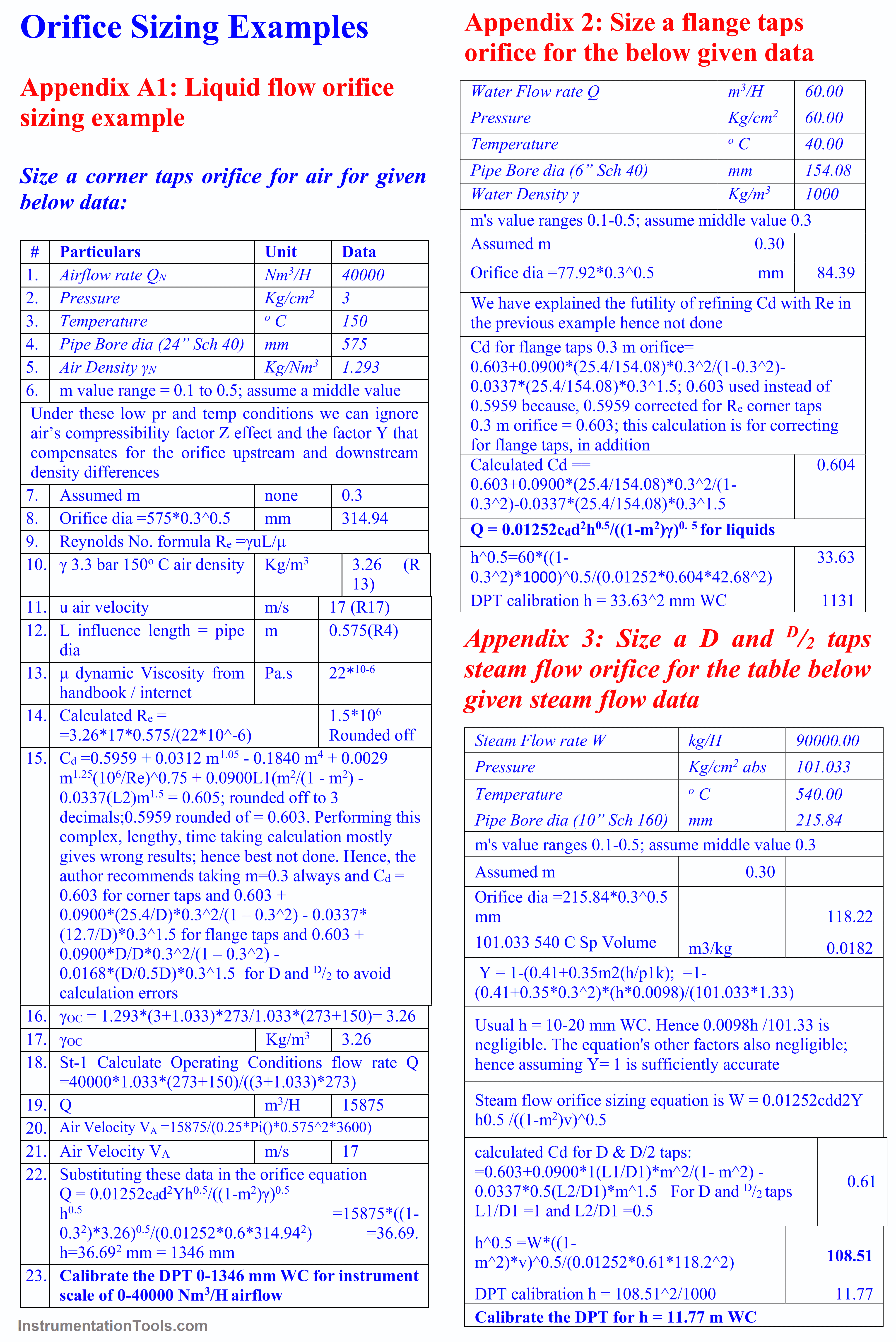
Answer to Reader’s Question 1:
Appendix 1 (A1) is a liquid flow orifice sizing, A-2 a gas, and A3 a steam sizing example. Sorry, newcomers may not easily understand these orifice sizing examples.
They may please ask an Instrument / Process engineer colleague (IPEC) to refresh their memory reading this article and walk them (readers) through the calculation steps. The reader who asked Q1 will find the answer herself/himself.
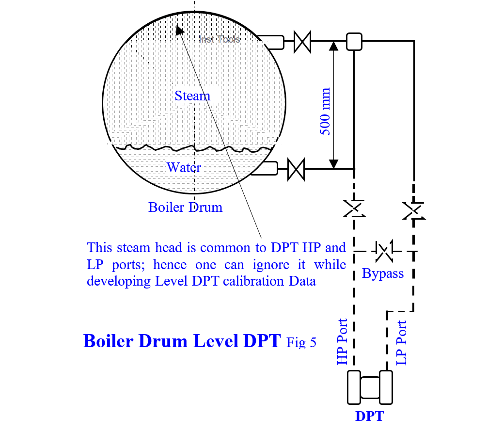
Answer to Reader’s Question 2:
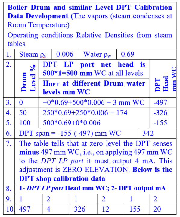
Sorry, the reader cannot connect the flow DPT to read boiler drum level also, because drum level DPT calibration involves ZERO ELEVATION, explained below:
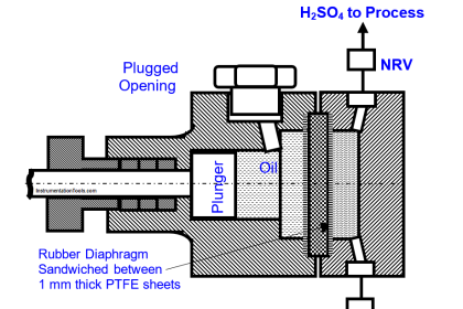
Reader’s Q-2 says the steam temp is 515o C but does not give the steam pressure; because of this high temperature, the author assumes 100-barG for steam pressure and develops the level DPT (fig 2) calibration data.
They show that DPTs with zero elevation capabilities are necessary for room temperature condensable into vapors liquid e.g., boiler drum level measurements.
As in Q-1, in case of difficulties, an instrument engineer colleague may refresh her / his knowledge reading this article and walk the reader through the calibration data development.
An Essential Information
This author finds condensate pot at the drum level taps and steam flow orifice taps. These were necessary for the bygone ‘high volumetric displacement’ flow/level measuring mercury float manometer days.
Such instruments’ HP and LP leads water levels differed considerably during rapid level/flow fluctuations. The large volume condensate pots minimized the level differences and minimized reading errors and the controllers’ wrong corrections till the readings settle down at the final value.
On the other hand, today’s pneumatic/electronic/smart DPT’s volumetric displacement is near zero and hence they read correctly even during high level/flow fluctuations.
However, the bygone day’s practice continues due to not knowing the condensate pots’ purpose and peoples’ mindset as below given parable shows:
Parable ‘Tying the Cat’
A guru taught many subjects to several sishyas (students) in his forest ashram. A starving cat wandered into the ashram. The guru pitied and gave asylum to the cat. It wandered here and there and disturbed the classes.
The guru assigned a pupil to tie the cat before the classes start. Years rolled on and tying the cat before classes start became a ritual. The guru reached the Lord’s feet, and a new guru took over. Still, tying the cat ritual continued as before. Few years later the cat died.
The new guru started the classes a week later, after one of the pupils found and tied a cat, i.e., not before the years and years followed tying the cat ritual completion!
Omitting the Condensate Pots (CP) Advantages
The advantages are:
- Condensate Pots (CPs) procuring / shop making huge expenses saved
- Condensate Pots (CPs) use involves few screwed connections, best avoided in high pressure and high temperature steam and vapor applications; they develop leaks too soon, waste expensive steam, pose repair expenses, and the instruments read wrong till leaks stop.
- The author has removed these in several steam DPT applications and saved enormous money sums and nuisance maintenance efforts.
- Even though few instrument catalogs show DPTs adapter flange bolted to around 100 mm long taps nozzles, avoid it. Rather connect DPT adapter flange bolted to min 800 mm long leads as in fig 1 to realize the below given advantages:
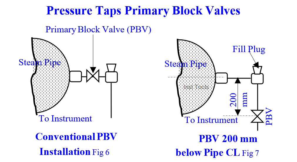
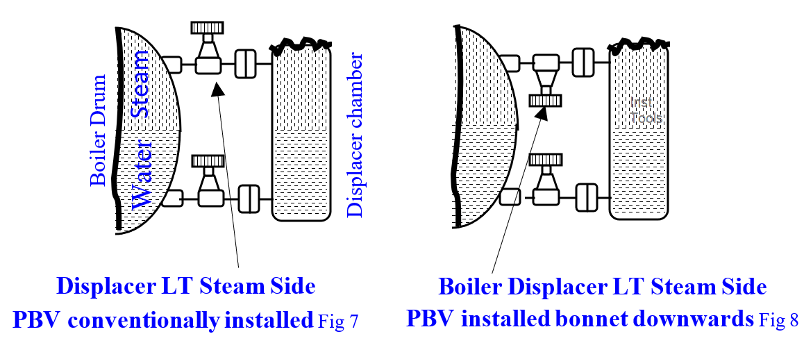
- We can locate the primary block valves (PBV) 200 mm below the pipelines (fig 7). This eliminates within few weeks developed steam flow DPT ¾” and Displacer Chamber steam side 2” PBVs gland bonnet leaks. This author idea avoids welding 300 Nos. ¾” and 25 Nos. displacer chamber steam side 2” PBVs yearly in a Fertilizer Plant
- The author guesses that hot steam / water mixture wetted, the conventionally mounted PBVs’ packing, and bonnet gaskets leak within weeks; but cold condensate only wetted, the relocated PBVs’ packing, and bonnet gaskets leak never.
- The simple modifications avoid the eyesore steam leaks, lost steam costs, welding new valves in position recurring costs which runs into several thousand rupees yearly.
- For LEVEL MEASURING TRANSMITTERS, omit 3‑way manifolds: simple equalizing leg (fig 5) suffices: Crews take the DPT into service thus:
- The HP and LP taps primary block valves are initially closed
- The crew loosen DPT HP and LP side vent plugs
- Open the fill plugs
- Fill Cold condensate in both leads till both leads are full
- Close the DPT vent plugs on air leaks stop
- Ensure both leads are full; this initial condensate fill prevents hot steam wetting the DPT sensing element and destroying it
- Tighten the fill plugs
- Open steam side PBV
- This applies drum pressure to the DPT HP, and LP port SIMULTANEOUSLY as three-way manifold valve does. It avoids drum pressure pressuring DPT one port and destroying the DPT sensor
- Hence three-way manifold is NOT NECESSARY
Orifice Sizing Examples