In the field of Industrial Automation, communication between active & passive devices is the most crucial task.
The communication occurs through various mediums such as Profibus, Profinet / Ethernet, Modbus RTU, and Modbus TCP, etc. Along with these mediums, the device must have standard communication protocol support to establish the connection.
In TIA Portal, we can establish communication between two CPUs using S7 Connection via Profinet and Industrial Ethernet.
Instructions
The following instructions are used for S7 Communication.
- GET
- PUT
Using the above instructions we can establish communication between S7 1500 and S7 1200 CPUs.
PUT
The PUT instruction sends the data to the Partner CPU.
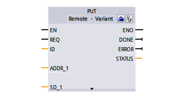
Input Pins
EN – The instruction shall be enabled only if this pin is healthy.
REQ – The instruction sends the data to Partner CPU on the Positive Pulse applied to this pin.
ID – This is the hardwired ID created automatically when we create PUT instruction.
ADDR_1 – The pin contains the address of Partner CPU, where data needs to be sent.
SD_1 – The pin contains the address of the Local CPU i.e. the data to be sent to Partner CPU.
GET Instruction
The GET instruction gets the data from the Partner CPU.
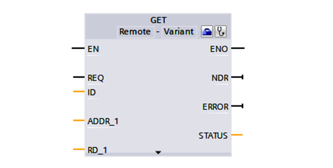
Input Pins
EN – The instruction shall be enabled only if this pin is healthy.
REQ – The instruction sends the data to Partner CPU on the Positive Pulse applied to this pin.
ID – This is the hardwired ID created automatically when we create PUT instruction.
ADDR_1 – The pin contains the address of the Local CPU, where data needs to be sent.
RD_1 – The pin contains the address of the Local CPU i.e. the data to be sent to Partner CPU.
The output pins for both the instructions are same.
Output Pins
ENO – Enable Output Pin
DONE – This pin indicates data transfer is done.
ERROR – This pin indicates a data transfer error.
STATUS – This pin indicates data transfer success / failure status.
PLC to PLC Communication using S7 Connection Configuration Steps
The S7 connection is a single-sided connection i.e. we can write the instruction in any one PLC to get or put data to another PLC.
We will test the PUT instruction in this example. On a similar front GET instruction is executed.
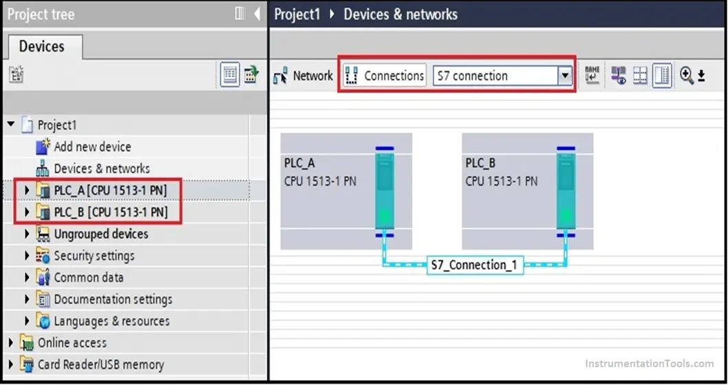
Step 1:
TIA Portal Hardware Configuration.
- Drag two PLC’s (PLC_A & PLC_B) into the hardware configuration window and select S7 Connection. Connect the PLCs using Profinet ports.
- We can select any type of PLC in the S7-1200 & S7-1500 series.
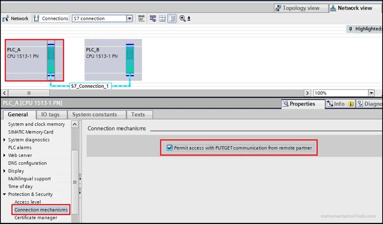
Step 2:
Permit Access to PLCs for PUT / GET Communication.
- Check the box as shown in the figure for permitting PLC PUT / GET Communication.
- Select Core of PLC -> Properties -> General ->Protection & Security -> Connection mechanism
Step 3:
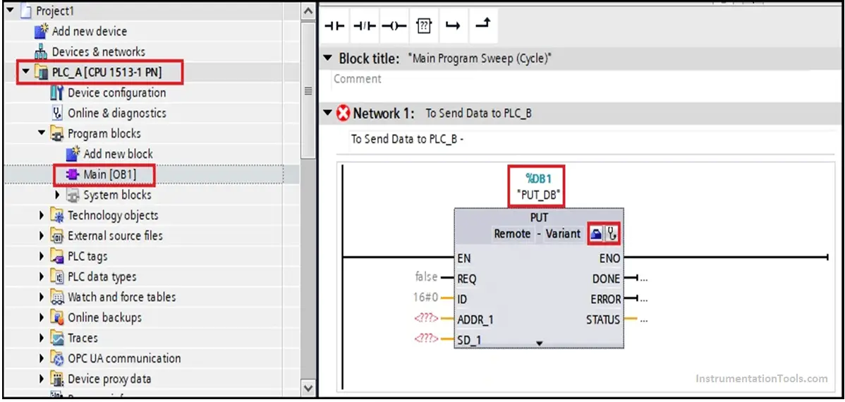
Call the PUT Instruction into ‘OB1’ of Local PLC and Set the Properties.
- We consider PLC_A as Source / Local PLC & PLC_B as Destination / Partner PLC. Hence, we have called PUT Instruction in OB1 of PLC_A.
- We have called PUT Instruction in Main Program Cycle ‘OB1’ of PLC_A.
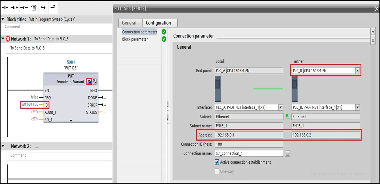
Connection Parameters:
Click on the Blue Icon on PUT Instruction.
The screen shall navigate to Configuration Parameters of PUT Instruction.
Select Partner CPU as PLC_B, other parameters shall be automatically selected.
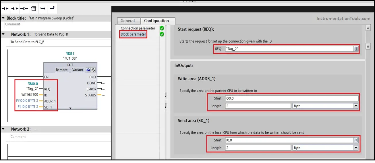
Block Parameters:
The block parameters are the same explained in the pin diagram above.
Tag_2 (M0.0) is data send request input.
Q0.0 is the address of PLC_B over which data shall be sent.
I0.0 is the address of PLC_A from which data shall be sent to PLC_B.
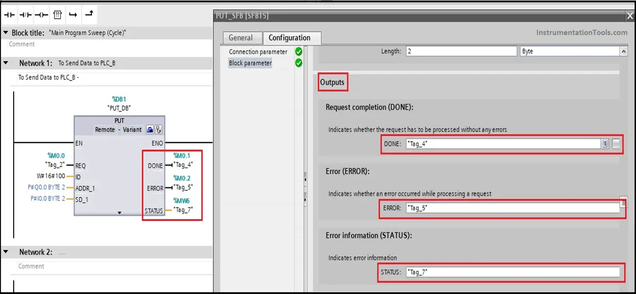
- The output block parameter selection is shown in the figure.
- Tag_4 shall indicate data transfer action done.
- Tag_5 shall indicate if any error occurs in data transfer.
- Tag_7 shall indicate data transfer status.
- We can use a separate DB address for mapping these outputs.
Step 4:
Start Simulation for both PLC_A & B and download the codes.
Step 5:
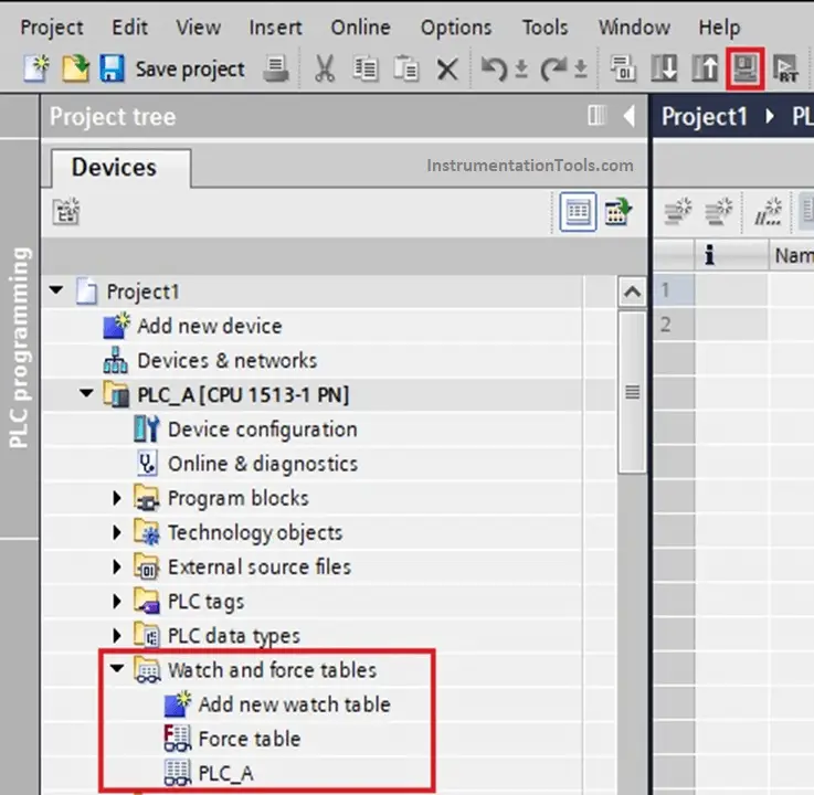
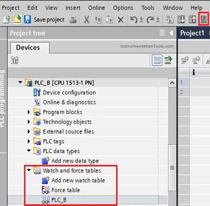
Testing using Watch Table for both PLC A & PLC B.
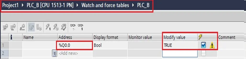
We have created separate watch tables for PLC_A & B. I0.0 is the source address in PLC_A and Q0.0 is the destination address in PLC_B.
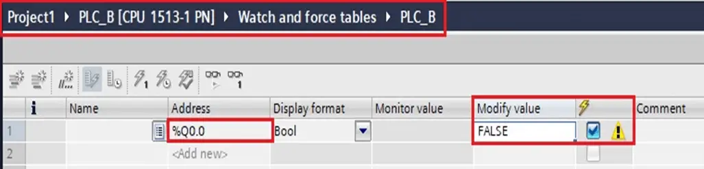
- In PLC_A watch table, force ‘FALSE’ value into I0.0 address.
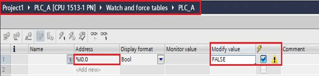
- In PLC_B watch table, the value of Q0.0 shall be ‘FALSE’.
- In PLC_A watch table, force ‘TRUE’ value into I0.0 address.
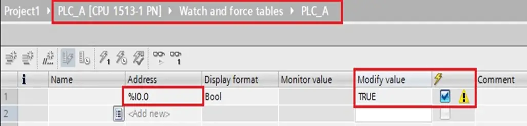
- In PLC_B watch table, the value of Q0.0 shall be ‘TRUE’.
Pros & Cons
It is very easy to establish. However, once communication is established it has no control or watch over data exchange.
It is not a secure method of data exchange as the PLC is available to any devices present over the network.
The data blocks (DB’s) with quantized / symbolic addressing type doesn’t support this method of data communication.
Conclusion
We studied one of the methods to establish communication between PLCs using PUT & GET Instruction in S7 Connection. It is very easy to establish and should be used over secure networks. The medium used is Profinet / Industrial Ethernet. We exercised PUT instruction to send data from PLC_A to PLC_B.
Author: NMG
If you liked this article, then please subscribe to our YouTube Channel for Instrumentation, Electrical, PLC, and SCADA video tutorials.
You can also follow us on Facebook and Twitter to receive daily updates.
Read Next:


This is very good PLC tutorial. Thnx