Primary Reformer – Each Turnaround done massive and expensive Tubes Repairs eliminated.
| Article Type: | Root Cause Analysis (RCA) |
| Category: | Mechanical |
| Equipment Type: | Pipelines and Miscellaneous Problems |
| Author: | S. Raghava Chari |
Note: This root cause analysis (RCA) is from real-time scenarios that happened in industries during the tenure of two or three decades ago. These articles will help you to improve your troubleshooting skills and knowledge.
Problem
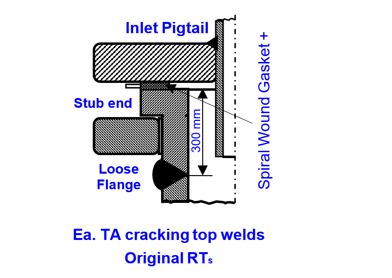
The entire 240 Nos. of Reformer Tubes’ top stub end to tube welds were found cracked at every turnaround (TA).
As tubes performed leaks free during service the plant concluded the cracks developed during the after shutdown cooling.
The’ repairs efforts and costs crippled the company finances each turnaround (TA) besides stressing the managers and crew to their limits each TA.
Primary Reformer
Primary Reformers (PR) are large furnaces containing rows of HK 40 – high nickel alloy steel – 150 mm OD x 22 mm WT Reformer Tubes (RT) filled with first layer and second layer catalysts.
Natural gas is the preferred feedstock and others e.g. Naphtha or fuel oil depending on availability and economics. Heated hydrocarbon vapors or NG feedstock mixed with 40‑bars 4000C superheated steam passes via the RTs.
External firing supports the mixture’s endothermic reforming into hydrogen and other component gases aka Reformed Gases (RFG).
An U‑shaped inlet pigtail connects the inlet header to each RT top. Similar outlet pigtail RT connects the tubs’ bottoms to the RFG collector. A collector receives RFG from 12 RTs.
The inlet and outlet pigtails connections allow the very high temperature 900o C RTs’ and connected system components’ stress-free thermal expansions.
The hot RFG from the collectors reach the gas main. It conveys the entire RFG to further processing plants, which deliver synthesis gas (75% H2 + 25% N2 mixture) for ammonia production.
Reformer Tube Failures
The plants post-commissioning 18 months run was excellent. During restart after the first Turnaround (TA), hissing air leaks at RT to stub end welds forced the plant to stop and investigate the problem.
Inspectors’ Dye Penetrant tests showed 75%circumferential through cracked welds of all the 240 Nos. of tubes.
The undaunted plant maintenance and operation crew completing the below listed considered near-impossible tasks rapidly and correctly restored Ammonia production within a week.
- Unbolted the inlet pigtails flanged joints
- Vacuumed out and saved the newly filled top and bottom catalysts layers for reuse.
- Cut the Outlet Pigtail (OPT) 100 mm away from welds to the RTs
- Lifted the entire 240 Nos. of RTs out of the reformer one at a time using a long boom hired crane
- Modified the phosphoric acid tanker chassis to rapidly transport the ‘to repair’ RTs to workshop and the repaired RTs back to the plant
- Shop crew cut the stub ends from the RTs. They edge prepared the stub ends and RTs ends for welding. An army surplus because of dirt-cheap installed horizontal boring mill came handy! It weld-edge prepared the 13 m long RT ends easily and at high rates
- Welders welded the lathe edge prepared stub ends to the mill edge prepared RTs
- Another crew hydro-tested the tubes to 1½*35 = 53 bars using chlorides free water
- While these tasks progressed city, several workshops turned out 250 Nos. socket weld sockets out of rush procured incolloy barstock. In addition, they made 250 Nos. inlet loose flanges. Fortunately, 31 mm thick Cr-Mo steel plates were in stock.
- Field crew cut the ½ m long 1¼” inlet pipe extension into the RT – process licensor suggestion
- Crew transported the readied RTs, put back in the reformer and welded back the OPT connections using the local shops made socket weld sockets.
- Operators filled catalysts
Thanks to careful planning and scheduling, and everyone working to achieve a challenging goal, as many tasks as practical progressed simultaneously round the clock.
Thus, the seemingly impossible suddenly imposed formidable tasks were over within just 6 days.
The Process Licensor’s (PL) Root Cause Analysis (RCA) solution
The PL expounded fancy theories as the cracks reason and suggested removing the inlet pigtails extending 1/3 meter inside the RT.
In addition, he recommended upgrading the carbon steel top flanges to 1¼ Cr-½ moly because of unsuitability for 35 bars 300o C hydrocarbon vapors service. after the 1/3 m protrusion removal.
The plant got the 240 Nos. of 1¼, ½ Moly inlet flanges made by the town’s several workshops using providential construction surplus 35 mm plates, implemented the suggestion and the reformer started in 6-days.
Problem Persists
Despite these improvements, the problems recurred during the next TA also. Fortunately, inspectors dye penetrant tests after RTs cooling to ambient temperature avoided many repeat tasks and saved time and avoided wasteful efforts.
The inspection engineers advised post-weld stress relief alleging that the combined weld residual stress and process pressure stress led to the cracks.
Maintenance handled this challenge too using improvised heating elements and controlled temperature raise and cooling systems and completed the TA in record time.
The weld crack problem surfaced during the 3rd TA also. This time the inspection advised pre-weld stress relief too. Still the problem surfaced after the 4th TA also.
End of Life of Reformer Tubes
By then the author the new maintenance manager insisted on installing upgraded material IN 529 bore machined RTs and avoiding top flange weld by hook or crook.
Bore machining eliminates the centrifugally cast RTs residual stresses and no top flange welds the ever-persisting weld crack problems. The plant management invited the process licensor (PL) to examine the proposal.
Since one out of the 20 Nos. of collectors, which receive the hot RFG from each RT posed weld crack problems the plant decided to replace the collectors too.
The PL’s visiting engineer during preliminary discussions concurred with the material upgrade and bore machining proposal; and revised tube wall thickness to 12 mm against HK-40’s 22 mm, because of IN 529’s far superior high temperature permissible stress.
However, he and the plant design group declaring impossible, challenged the author to present in two days a way to eliminate top flange weld.
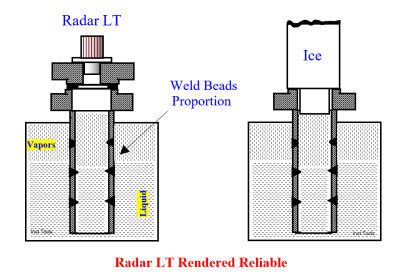
No weld IPT flanged joint is possible! The author thought of an idea in a day: Do not weld a stub end. Instead, make the last RT piece longer to include the stub length. Retain the loose flange by split rings inserted in grooves cut on RTs near the top (fig 2).
This way simple spiral wound filler ring would suffice saving on gaskets costs also. The PL’s visiting engineer appreciated and congratulated the author.
However, he wanted his Denmark Design Department (DDD) to evaluate and finalize the design details. The DDD also appreciated the idea so much that all their future reformers RTs are of this design.
The author rather preferred 16 mm WT to use a wider gasket to be doubly sure. The PL agreed.
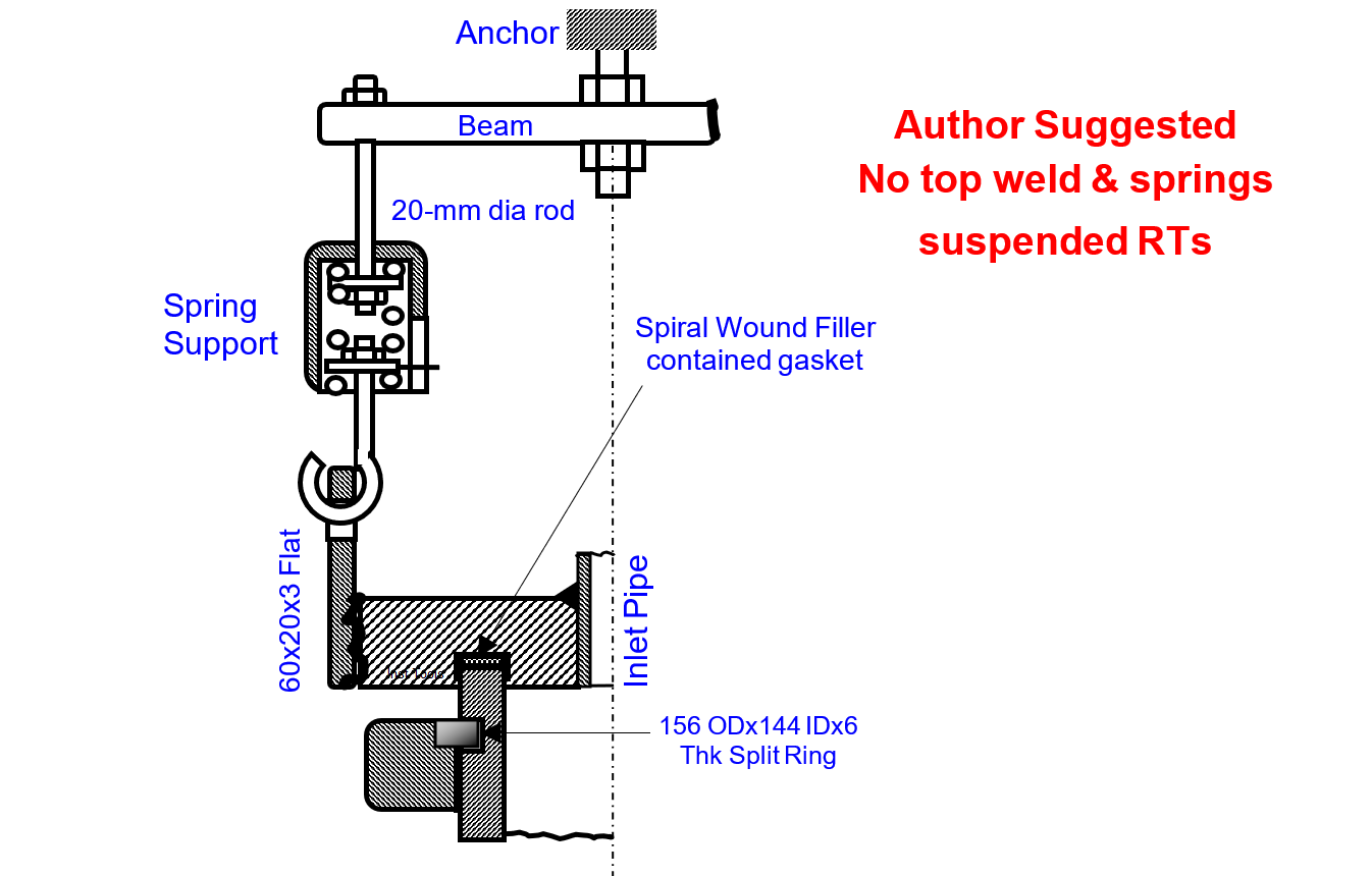
Finally, all settled for 150 OD x 16 mm WT RTs and 3 mm deep grooves held 156 OD x 144 ID x 6 mm thick split rings retained inlet flanges (fig 2); i.e. no weld at the RT top. Material of the flanges and split rings is 1¼, ½ Moly.
Spring Supports Eliminate RT bow problems
In addition, the PL accepted the Author proposal to add springs supports. The crew connects the left spring support to the cross beam bolted to the anchor with no load on the spring.
Similarly, they bolt the right support too. The turnbuckle helps in this task. They adjust the scale to read zero loads.
They adjust the turnbuckle to stretch and lengthen the springs till each spring carries around 300 Kg RT weight. I.e. both the springs carry 600 Kg of the RT’s 900 Kg weight before reformer firing.
RTs final 900o C operating temperature expansion, releases around 600 Kg spring force. Still the springs pull the tube upward with 300 kg force and prevent the past serious bowing problem.
The new design RTs Advantages
The new design RTs advantages are:
- Expensive incolloy stub ends, their welding and cracks problems, laborious and expensive repairs and consequent extended TAs vanished
- Consequently, the new design RTs cost 30% less than the original design RTs
- Perhaps gasket vendors’ tests would have confirmed 12-mm wide gaskets adequacy and saved on RT purchase costs still more. Alternatively, perhaps 16 mm WT for about 200 mm from RT top would have inexpensively met if larger gasket area was indeed necessary,
- Just filler rings cost 60% less than the formerly used retainer ring gaskets; in addition, the filler rings alone are lot easier to install. Thus the plant saves every turnaround. The contained gasket is blowout proof.
- Thanks to lesser gasket area overall flange dimensions and hence bolt loads and in turn bolts sizes are 25% less, saving purchase costs, installation times and associated costs.
- The spring supports eliminate the bowing and the resultant weakening of the RT and promote their life expectancy.
- Last, but not the least, RT bore increase enables 10% more catalyst fill and thus 10% capacity increase, or in other words longer times between catalyst changes for the same gas throughput as in the past i.e. longer interval between TA.
Problems Disappear
The plant ordered 132 RT and 11 Collectors on a vendor and the same on another vendor. This order leaves 10% spares for the 240 RT and 20 Collectors in service.
The vendors supplied the tubes in time for the TA, but not the collectors due to manufacturing problems.
The Author suggestion solved the plant management’s dilemma: just replace the tubes alone, as these only fail and not the collectors. In addition, collectors’ max operating temperature is 8700C well below even HK‑40’s max permissible temperature, hence, no time-based replacement necessary. The plant can schedule collector change later based on condition monitoring results.
Conclusion
The innovative idea split rings held inlet pig tail loose flange joints are absolutely problems free because of simple “no welds; no weld cracks!”
In addition, the RTs are 25% cheaper. Interestingly random 10 Nos. retired HK‑40 RTs dye checks identified all top welds cracked; maybe the remaining 230 Nos. HK-40 RT’s top welds too cracked! It shows that even pre and post weld stress reliefs don’t solve top weld crack problems.
The author suggested no top weld is the only solution. The PL has standardized the Author split ring retained lose flange RT inlet connection for their reformers.
The Author suggestion to replace RTs only without waiting for the collector’s deliveries also paid well. Had the HK-40 RTs continued, many more HK 40 tubes than in the past would have burst, necessitating expensive and hazardous pigtail nipping, consequent RFG and hence 50 – 60 T/d less ammonia production. In addition, the nipped PT need expensive new replacements with the new RT during the following TA.
The new IN 519 RTs eliminated all these. Vanished HK-40 RT top welds cracks repairs benefits if quantified would run into several recurring millions yearly!
In short, the Plant and Process licensor reap recurring immense financial gains and the author immense one-time job satisfaction only!
Author: S. Raghava Chari
Do you face any similar issues? Share with us through the below comments section.
If you liked this article, then please subscribe to our YouTube Channel for Instrumentation, Electrical, PLC, and SCADA video tutorials.
You can also follow us on Facebook and Twitter to receive daily updates.
Read Next:
- Leaking Plug Valves
- Flange Joint Problems
- Pipe Elbow Sudden Burst
- Fan Motor Journal Bearing Failures
- Fired Boiler Induced Draft Fan Failures


Dear Sir / Madam
I would like to know the source of manufacturers in india for reformer pig tail / U‑shaped pigtail / hairpin bend pigtail.
Please guide us
My contact No: + 91 44 2594 5320.
Mobile No: + 91 94433 07660
Regards
S GANAPATHY SUBRAMANIAN
SENIOR OFFICER – PURCHASE
MADRAS FERTILIZERRS LIMITED
MANALI, CHENNAI – 600068.
TAMILNADU, IINDIA
Dear Ganapathy
I remember Mr. Subramaniam Purchase Officer who used to meet me often for clarifications on items from my Purchase Requests (1970-87). Maybe you are his son. Sorry I am unable to answer your ‘pigtails query’ as I now live in Fremont CA USA with my son and out of contact with India Markets. I hope MFL is doing fine and many of my day’s youngsters are holding the MFL flag high doing STILL BETTER. Feel free to call me WhatsApp +1 925 202 5670; please keep in mind our Pacific Standard Time is 12 hours behind IST
Raghava Chari