As the generator is coupled with a steam turbine, we shall discuss the measurement of some Electrical parameters such as Voltage, Current, Power, Frequency, and Energy are the major parameters measured.
Voltage
- The other names for voltage are Potential Difference, Electromotive Force (EMF), and pressure of an electrical circuit.
- This voltage is measured with the help of a voltmeter.
- Voltmeters are standard items on switchboards and control panels.
- They are basically single-circuit elements therefore when three phases are to be indicated, either three instruments are used or one with a multipoint switch.
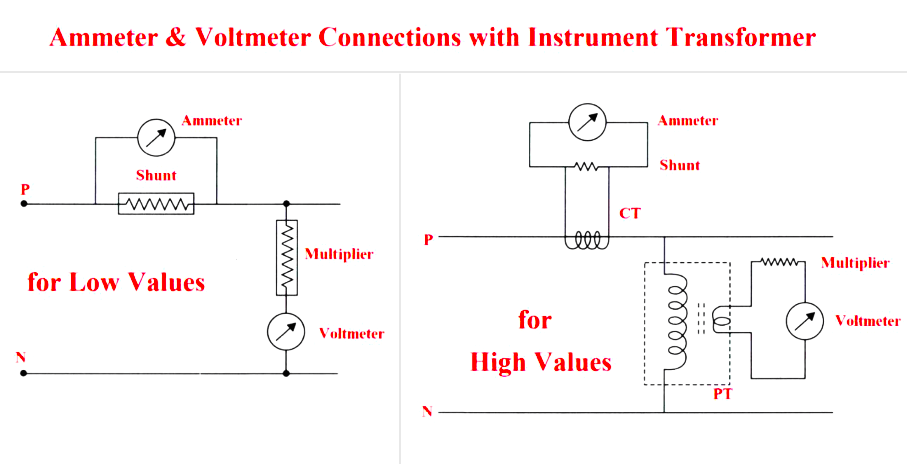
- The voltmeter is connected across the line and is a high-impedance one.
- The voltmeter ranges can be varied with high-value resistors connected in series; such resistors are called voltmeter multipliers.
- For high voltages, the Potential Transformer (PT) is connected to the main line called the primary, and the voltmeter is connected to the secondary.
- Voltmeters are normally of moving iron types.
- Moving coil meters can also be used but in conjunction with rectifiers.
Current
- The quantity of electrical current flowing through a circuit is measured by an ammeter.
- The low-impedance ammeter is connected in series with the line.
- Ammeters connected in parallel to the instruments are accommodated to various ranges with small value resistances.
- For the measurement of a very large current, these current transformers are connected to the main lines called primary, and the instruments are connected to their secondary.
- The Current Transformer (CT), is used to measure large currents.
- Normally the power line itself is considered as primary windings of the current transformer.
- The secondary windings are practically short-circuited by the measuring ammeters.
- Current Transformers convert the current to be measured into conveniently measurable secondary current preserving values and phases in proportion.
- Ammeters are almost identical to voltmeters, but for their input impedances and mode of connections.
Power (Active)
- The power of a direct current (always active) can be found in one ammeter and one voltmeter.
- Both voltage and current readings can be multiplied to get the required power.
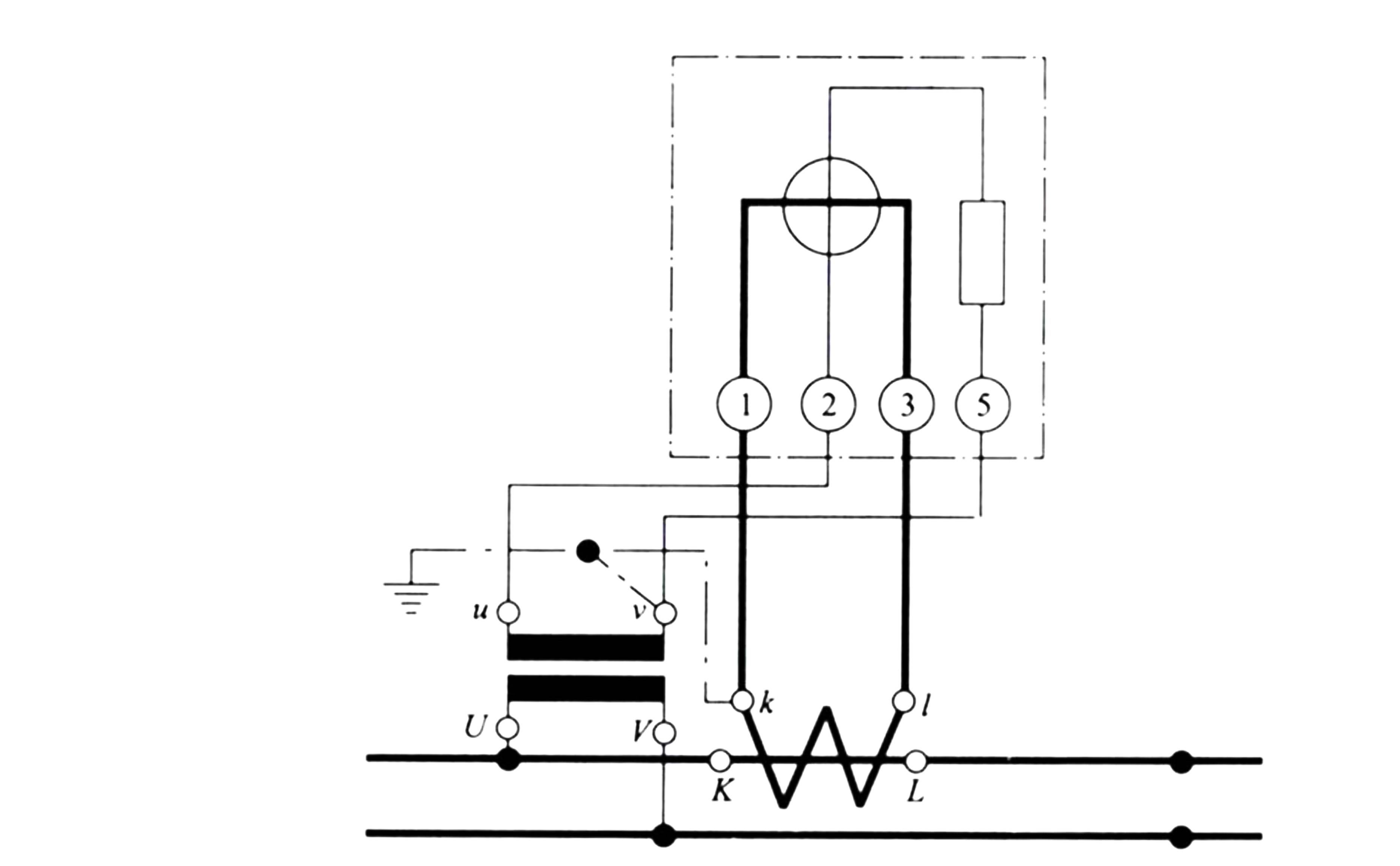
- D.C. power can be measured by an Electro-dynamic wattmeter with a voltage coil and current coil.
- Instrument transformers are connected such that the voltage path is connected ahead of the current path.
- For safety reasons, the secondary of both transformers are connected to a common earth.
- Cosφ is the phase angle between the voltage and the current.
- For an alternating current circuit, the active power is given by P= V*I*Cosφ
- The active power for a 3φ phase system is the total of the three components.
For star connection, it is given by.
P = 3 Vp I cos φ
For delta connection, it is given by.
P= √3 VL I cos φ
Where
V = RMS values of voltage
I = RMS values of current
P = Total power
Cosφ = Power Factor
Vp = Phase to neutral Voltage
VL= Line Voltage
Some of the common methods used in power plants are
Three-wattmeter is the most accurate method with indications and mechanical adder having a common shaft.
Three-wattmeter Method (Three-phase three-wire system)
WR+WY+WB = (VRC * IR) + (VYC * IY) + (VBC * IB)
WR+WY+WB = (VRN * IR) + (VYN * IY) + (VBN * IB)
WR+WY+WB = PR +PY+ PB = Total Power
It is observed that the sum of the three individual wattmeter readings (WR+WY+WB) indicates the total power consumed by the load (PR +PY+ PB).
Three–Wattmeter Method (3φ 4-wire System)
WR+WY+WB = (VRC * IR) + (VYC * IY) + (VBC * IB)
WR+WY+WB = (VRN * IR) + (VYN * IY) + (VBN * IB)
WR+WY+WB = PR +PY+ PB
The total power consumed by load is given by the summation of three wattmeters.
Two Wattmeter Methods
- This is the most commonly used method for measuring three-phase power.
- It is useful for both balanced and unbalanced loads.
- The sum of two watt-meter readings will be equal to the total power consumed as given below.
- Power consumed by the load
P= VRN * IR + VYN * IY + VBN * IB
Summation of wattmeter readings
W = W1 + W2
W = (VRN -VYN)* IR + (VBN – VYN) * IB
W = (VRN * IR) +(VBN* IB) + VYN (-IR – IB)
By Kirchhoff’s law, we know that, IR+IB+IY=0, or IR -IB = IY
W1+W2= VRN * IR + VYN * IY + VBN * IB = P
For delta connection load
P = VRB * IR + VYR * IY + VBY * IB
W₁ + W₂ = -VYR * (IR-IY) + VBY *(IB-IR)
P= VRB * IR + VYR * IY + VBY * IB
Where (VYR + VBY +VRB = 0)
It can be proved that the total power
W1 + W2= 3*V*I*cos φ
W1 – W2 =√3*V*I*sin φ
Hence,
tanφ = √3*[(W1 – W2)/(W1 + W2)]
Power factor Cosφ = Cos [tan-1 {√3 ((W1 – W2)/ (W1 + W2))}]
Energy
- In terms of watt-hour or kilowatt-hour (kWh).
- The kWh is defined as the energy supplied or consumed at an average rate of 1 kilowatt for one hour.
- In commercial metering, 1 kWh is called 1 unit of energy.
- Energy meters are used for the measurement of energy.
- Energy meters have moving systems that revolve continuously, it deflects only through a fraction of a revolution
- In energy meters, the speed of revolution is proportional to the power and the total number of revolutions made by the meter moving system over a given period is proportional to the energy.
- The most commonly used energy meters are Induction type instruments.
- Such meters have lower friction and a higher torque/weight ratio.
- These meters are inexpensive but accurate.
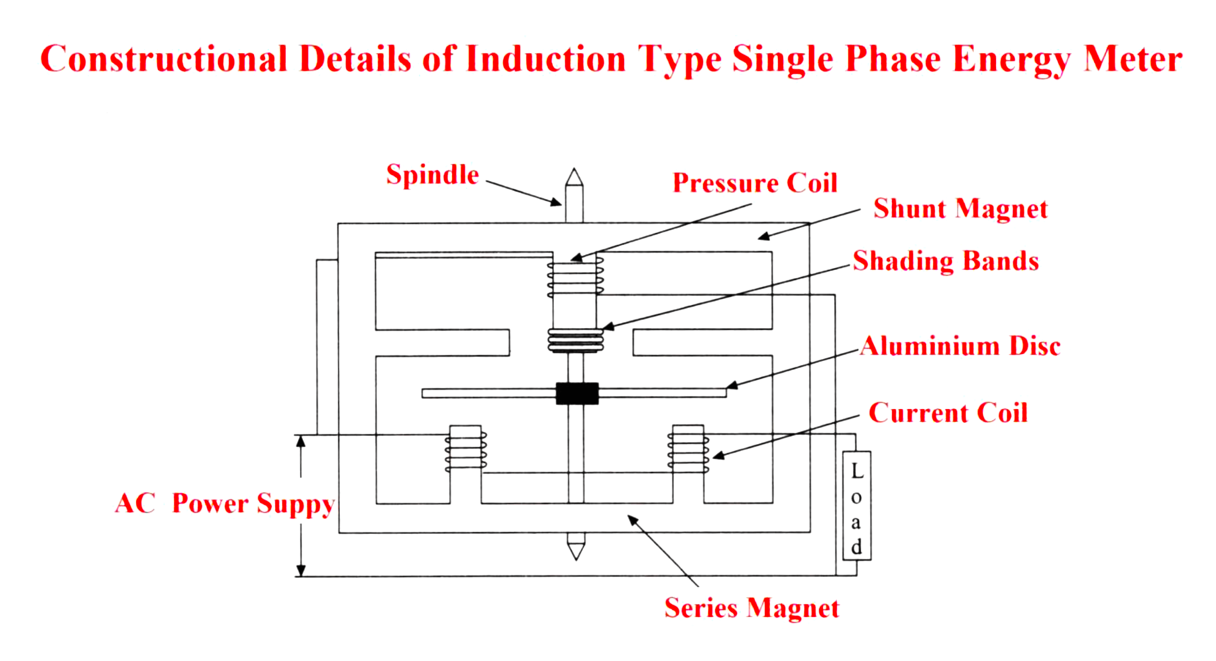
- Constructional details of an induction type single phase energy meter are shown schematically in the Figure above
- The operating system consists of two electromagnets.
- The current coil is wound on the series magnet and the pressure coil is wound on the shunt magnet.
- Shading bands made of copper are used to bring the flux produced by the shunt magnet exactly in quadrature with the applied voltage.
- The moving system consists of a light aluminum disc mounted on a spindle.
- The disc is placed in the space between the series and shunt magnets.
- The disc is positioned such that it intersects the flux produced by both magnets.
- The deflecting torque on the disc is produced by the interaction between these fluxes and the eddy current they induce in the disc.
- As there is no control spring, continuous rotation is possible.
- The braking system consists of a permanent magnet positioned near the edge of the aluminum disc whose position is adjustable.
- When the braking torque becomes equal to the operating torque, the disc rotates at a steady speed.
- A registering system consisting of a train of reduction gears makes counting in numerical value possible.
Frequency
- Frequency meters are more convenient for most practical purposes.
- These indicate the generated power frequency.
- a vibrating reed frequency meter mainly consists of more thin steel strips called reeds arranged close electromagnet.
- The electromagnet is laminated and its winding is connected, in series with a resistance, across the supply whose frequency is to be measured.
- The external connection is the same as the voltmeter.
- The reeds are made with slight differences in that their natural frequencies are different.
- These reeds are arranged in ascending order of frequency from 47 cycles per second up to 53 cycles per second.
- The natural frequency of the first reed is 47 cycles per second, and the next reed is 47½ cycles per second, and so on.
- The magnetism of the electromagnet alternates with the supply frequency and exerts an attracting force when the meter is in use.
- The one whose natural frequency is matching with the supply frequency will vibrate appreciably showing the supply frequency.
- The flags at the top of the reeds are painted with the corresponding frequency so that one can read directly the frequency by observing the reed which is vibrating most.
- A great advantage of this type of meter is that its indications are independent of the applied voltage and waveforms.