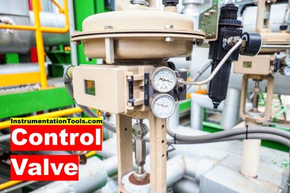
Standard control valves can handle a wide range of control applications. The range of standard applications can be defined as being encompassed by atmospheric pressure and 6000 psig (414 bar), 150F (65C), and 450F (232C), flow coefficient Cv values of 1.0 and 25000, and the limits imposed by common industrial standards.
Certainly, corrosiveness and viscosity of the fluid, leakage rates, and many other factors demand consideration even for standard applications.
Perhaps the need for careful consideration of valve selection becomes more critical for applications outside the standard limits mentioned above.
Here we are going to discuss some special applications and control valve modifications useful in controlling them, designs and materials for severe service, and test requirements useful for control valves used in nuclear power plant service.
Special Control Valves
High Capacity Control Valves
Generally, globe-style valves larger than 12-inch, ball valves over 24-inch, and high-performance butterfly valves larger than 48-inch fall in the special valve category. As valve sizes increase arithmetically, static pressure loads at shutoff increase geometrically.
Consequently, shaft strength, bearing loads, unbalanced forces, and available actuator thrust all become more significant with increasing valve size. Normally maximum allowable pressure drop is reduced on large valves to keep design and actuator requirements within reasonable limits.
Even with lowered working pressure ratings, the flow capacity of some large-flow valves remains tremendous.
Noise levels must be carefully considered in all large-flow installations because sound pressure levels increase in direct proportion to flow magnitude.
To keep valve-originated noise within tolerable limits, large cast or fabricated valve body designs have been developed. These bodies, normally cage-style construction, use unusually long valve plug travel, a great number of small flow openings through the wall of the cage, and an expanded outlet line connection to minimize noise output and reduce fluid velocity.
Naturally, actuator requirements are severe, and long-stroke, double-acting pneumatic pistons are typically specified for large-flow applications. The physical size and weight of the valve and actuator components complicate installation and maintenance procedures.
Installation of the valve body assembly into the pipeline and removal and replacement of major trim parts require heavy-duty hoists.
Maintenance personnel must follow the manufacturers’ instruction manuals closely to minimize the risk of injury.
Low Capacity Valves
Many applications exist in laboratories and pilot plants in addition to the general processing industries where control of extremely low flow rates is required.
These applications are commonly handled in one of two ways. First, special trims are often available in standard control valve bodies.
The special trim is typically made up of a seat ring and valve plug that have been designed and machined to very close tolerances to allow accurate control of very small flows. These types of constructions can often handle Cv’s as low as 0.03.
Using these special trims in standard control valves provides the economy by reducing the need for spare parts inventory for special valves and actuators. Using this approach also makes future flow expansions easy by simply replacing the trim components in the standard control valve body.
Control valves specifically designed for very low flow rates also handle these applications. These valves often handle Cv’s as low as 0.000001.
In addition to the very low flows, these specialty control valves are compact and lightweight because they are often used in laboratory environments where very light schedule piping/tubing is used.
These types of control valves are specially designed for the accurate control of very low flowing liquid or gaseous fluid applications.
High-temperature Control Valves
Control valves for service at temperatures above 450°F (232°C) must be designed and specified with the temperature conditions in mind.
At elevated temperatures, such as may be encountered in boiler feedwater systems and superheater bypass systems, the standard materials of control valve construction might be inadequate.
For instance, plastics, elastomers, and standard gaskets generally prove unsuitable and must be replaced by more durable materials.
Metal-to-metal seating materials are always used. Semi-metallic or laminated flexible graphite packing materials are commonly used, and spiral wound stainless steel and flexible graphite gaskets are necessary.
Cr-Mo steels are often used for the valve body castings for temperatures above 1000°F (538°C). ASTM A217 Grade WC9 is used up to 1100°F (593°C).
For temperatures up to 1500°F (816°C) the material usually selected is ASTM A351 Grade CF8M, Type 316 stainless steel.
For temperatures between 1000°F (538°C) and 1500°F (816°C), the carbon content must be controlled to the upper end of the range, 0.04 to 0.08%.
Extension bonnets help protect packing box parts from extremely high temperatures. Typical trim materials include cobalt-based Alloy 6, 316 with alloy 6 hard facing and nitrided 422 SST.
Cryogenic Services Valves
Cryogenics is the science dealing with materials and processes at temperatures below minus 150F (65C).
For control valve applications in cryogenic services, many of the same issues need consideration as with high temperature control valves. Plastic and elastomeric components often cease to function appropriately at temperatures below 0F (–18C). In these temperature ranges, components such as packing and plug seals require special consideration.
For plug seals, a standard soft seal will become very hard and less pliable thus not providing the shut-off required from a soft seat. Special elastomers have been applied in these temperatures but require special loading to achieve a tight seal. Packing is a concern in cryogenic applications because of the frost that may form on valves in cryogenic applications.
Moisture from the atmosphere condensates on colder surfaces and where the temperature of the surface is below freezing, the moisture will freeze into a layer of frost. As this frost and ice forms on the bonnet and stem areas of control valves and as the stem is stroked by the actuator, the layer of frost on the stem is drawn through the packing causing tears and thus loss of seal.
The solution is to use extension bonnets which allow the packing box area of the control valve to be warmed by ambient temperatures, thus preventing frost from forming on the stem and packing box areas. The length of the extension bonnet depends on the application temperature and insulation requirements. The colder the application, the longer the extension bonnet required.
Materials of construction for cryogenic applications are generally CF8M body and bonnet material with 300 series stainless steel trim material. In flashing applications, hard facing might be required to combat erosion.
Customized Characteristics and Noise Abatement Trims
Although control valve characteristics used in standard control valves meet the requirements of most applications, often custom characteristics are needed for a given application.
In these instances, special trim designs can be manufactured that meet these requirements. For contoured plugs, the design of the plug tip can be modified so that as the plug is moved through its travel range, the unobstructed flow area changes in size to allow for the generation of the specific flow characteristic.
Likewise, cages can be redesigned to meet specific characteristics as well. This is especially common in noise abatement type trims where a high level of noise abatement may be required at low flow rates but much lower abatement levels are required for the higher flow rate conditions.
Control Valves for Nuclear Plants
Since 1970, U.S. manufacturers and suppliers of components for nuclear power plants have been subject to the requirements of Appendix B, Title 10, Part 50 of the Code of Federal Regulations entitled Quality Assurance Criteria for Nuclear Power Plants and Fuel Reprocessing Plants.
The U.S. Nuclear Regulatory Commission enforces this regulation. Ultimate responsibility of proof of compliance to Appendix B rests with the owner of the plant, who must in turn rely on the manufacturers of various plant components to provide documented evidence that the components were manufactured, inspected, and tested by proven techniques performed by qualified personnel according to documented procedures.
In keeping with the requirements of the Code of Federal Regulations, most nuclear power plant components are specified in accordance with Section III of the ASME Boiler and Pressure Vessel Code entitled Nuclear Power Plant Components. All aspects of the manufacturing process must be documented in a quality control manual and audited and certified by ASME before actual manufacture of the components.
All subsequent manufacturing materials and operations are to be checked by an authorized inspector.
All valves manufactured in accordance with Section III requirements receive an ASME code nameplate and an N stamp symbolizing acceptability for service in nuclear power plant applications.
Section III does not apply to parts not associated with the pressure–retaining function, to actuators and accessories unless they are pressure retaining parts, to deterioration of valve components due to radiation, corrosion, erosion, seismic or environmental qualifications, or to cleaning, painting, or packaging requirements.
However, customer specifications normally cover these areas. Section III does apply to materials used for pressure retaining parts, to design criteria, to fabrication procedures, to non-destructive test procedures for pressure retaining parts, to hydrostatic testing, and to marking and stamping procedures.
ASME Section III is revised by means of semi-annual addenda, which may be used after date of issue, and which become mandatory six months after date of issue.
Valves Subject to Sulphide Stress Cracking
Most ferrous metals can become susceptible to sulphide stress cracking (SSC) due to hardening by heat treatment and/or cold work. Conversely, many ferrous metals can be heat treated to improve resistance to SSC.
Carbon and low-alloy steels should be heat treated to a maximum hardness of 22 HRC to improve resistance to SSC.
Cast iron is not permitted for use as a pressure-containing member in equipment covered by some American Petroleum Institute standards and should not be used in non-pressure containing internal valve parts without the approval of the purchaser.
Austenitic stainless steels are most resistant to SSC in the annealed condition; some other stainless steels are acceptable up to 35 HRC.
Copper-base alloys are generally not to be used in critical parts of a valve without the approval of the purchaser.
Some high-strength alloys are acceptable under specified conditions.
Chromium, nickel, and cadmium plating offer no protection from SSC.
Weld repairs or fabrication welds on carbon and low-alloy steels require post-weld heat treatment to assure a maximum hardness of 22 HRC.
Conventional identification stamping is permissible in low stress areas, such as on the outside diameter of line flanges.
The standard precludes using ASTM A193 Grade B7 bolting for some applications. Therefore, it might be necessary to derate valves originally designed to use this bolting.
Read Next:
- Quiz on Control Valves
- Control Valve Noise
- PLC and Solenoid Valve
- Types of Valve Actuators
- Valve Recommended Practices


150F (–101C), and 450F (232C), mistake in convertior, 150F is 65.5556 C