A “current to pressure” converter (I/P) converts an analog signal\ (4 to 20 mA) to a proportional linear pneumatic output (3 to 15 psig).
Its purpose is to translate the analog output from a control system into a precise, repeatable pressure value to control pneumatic actuators/operators, pneumatic valves, dampers, vanes, etc.
Principle :
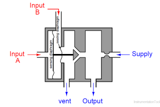
Its force balance principle is a coil suspended in a magnetic field on a flexible mount.
At the lower end of the coil is a flapper valve that operates against a precision ground nozzle to create a backpressure on the servo diaphragm of a booster relay.
The input current flows in the coil and produces a force between the coil and the flapper valve, which controls the servo pressure and the output pressure.
Also Read : Current to Pressure (I/P) Converter Theory
Calibration :
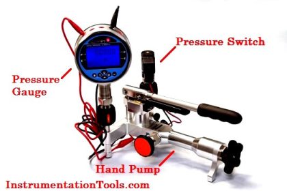
Required Apparatus:
1. Air Filter Regulator
2. I/P Converter
3. Master Pressure gauge (For Measurement of I/P Output pressure)
4. mA Source (to feed mA to I/P Converter)
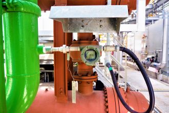
Calibration Setup :
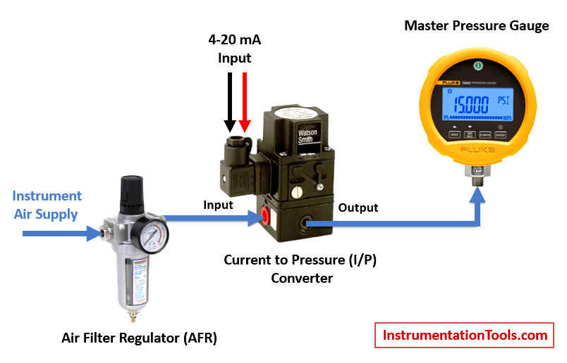
Calibration Procedure :
- Inlet air supply to be set at 20 psi in AFR
- Feed 4mA from source to I/P converter
- Observe master pressure gauge , it should show 3psi
- If it is not showing (3psi) adjust I/P ZERO up to obtain the 3psi
- Feed 20mA from source to I/P converter
- Observe master pressure gauge , it should show 15 psi
- If it is not showing 15 psi- adjust I/P SPAN up to obtain the 15 psi
- After completion of above procedure again feed 4mA-observe 3psi 20mA-observe 15psi
- Up to achieve the correct output from I/P converter repeat the step 2 to 7.
After calibration following to be done:
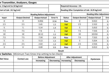
- All the readings to be entered in calibration report.
- Calibration sticker to be adhesived.


Very clear and simple explanation, perfect, thank you
I don’t understand why 4mA corresponds to 3 psi?Could you help me?!
same reason why you don’t use 0mA. if the pressure drops below 3PSI, the line is probably disconnected of you have a bad leak.
3psi is the minimum, below that you have a problem.
Those are the standard lower limits of calibration for current and pressure respectively in instrumentation. Same way the upper limits are 20mA and 15psig. So as the topic is trying to explain conversion from one signal to the other, there is need to understand how each corresponds to the other