SCADA (supervisory control and data acquisition) is a category of software applications for controlling industrial processes, which is the gathering of data in real-time from remote locations in order to control equipment and the operating process conditions.

In this post, we are going to learn how to establish a connection between SCADA software and any device that has the ability to communicate over the Modbus protocol.
What is Meant by a SCADA Driver?
Professor Jose Soares Augusto explains the meaning of a SCADA driver that it is a low-level software component, usually written in C or even in assembly language, whose main function is to “link”, or integrate, an external hardware or software component into the system.
In a PC operating system, you have drivers for “video cards”, for “audio cards” for the USB protocol, etc.
The SCADA driver usually is a “satellite” component in the operating system software of a device that needs to connect to an industrial (the main area of deployment of these systems) SCADA network.
Notice that the methodology of working for a Driver is kindly different from the Server principle of working.
A driver is something related to hardware. It basically contains a mapping/translation so that an operating system can communicate with the hardware.
Client and Server, on the other hand, are related to each other. In the simplest terms, a client is an application that takes input, sends data to a Server to be processed, gets returned information, and presents the output.
Steps for Creating a Modbus Protocol in Indusoft Web Studio
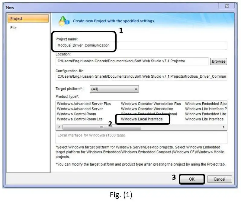
Creating a new project as shown in Fig. (1).
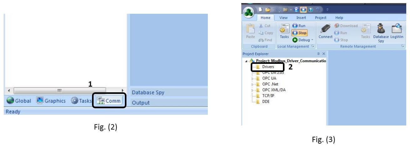
To establish the Modbus driver, we have to go to the Communication list at the project explorer as shown in Fig. (2).
Then to add the driver right click on the driver folder in the project tree that is shown in Fig. (3) and select Add Driver.
The driver’s window will pop up as shown in Fig. (4) now you can choose the suitable driver for your controller or your interfacing hardware.

As shown, we select the Modbus RTU driver via TCP, then you have to press select to add it to your project drivers and OK.
Now as shown in Fig. (5) the Modbus driver is successfully loaded to your project and by clicking on the Main driver sheet you can setup the driver parameters and tags.
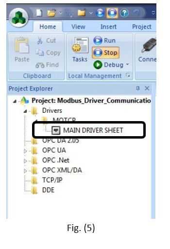
To configure the MAIN DRIVER SHEET, right-click on the icon, and select Open from the pop-up, or just double-click on the icon.
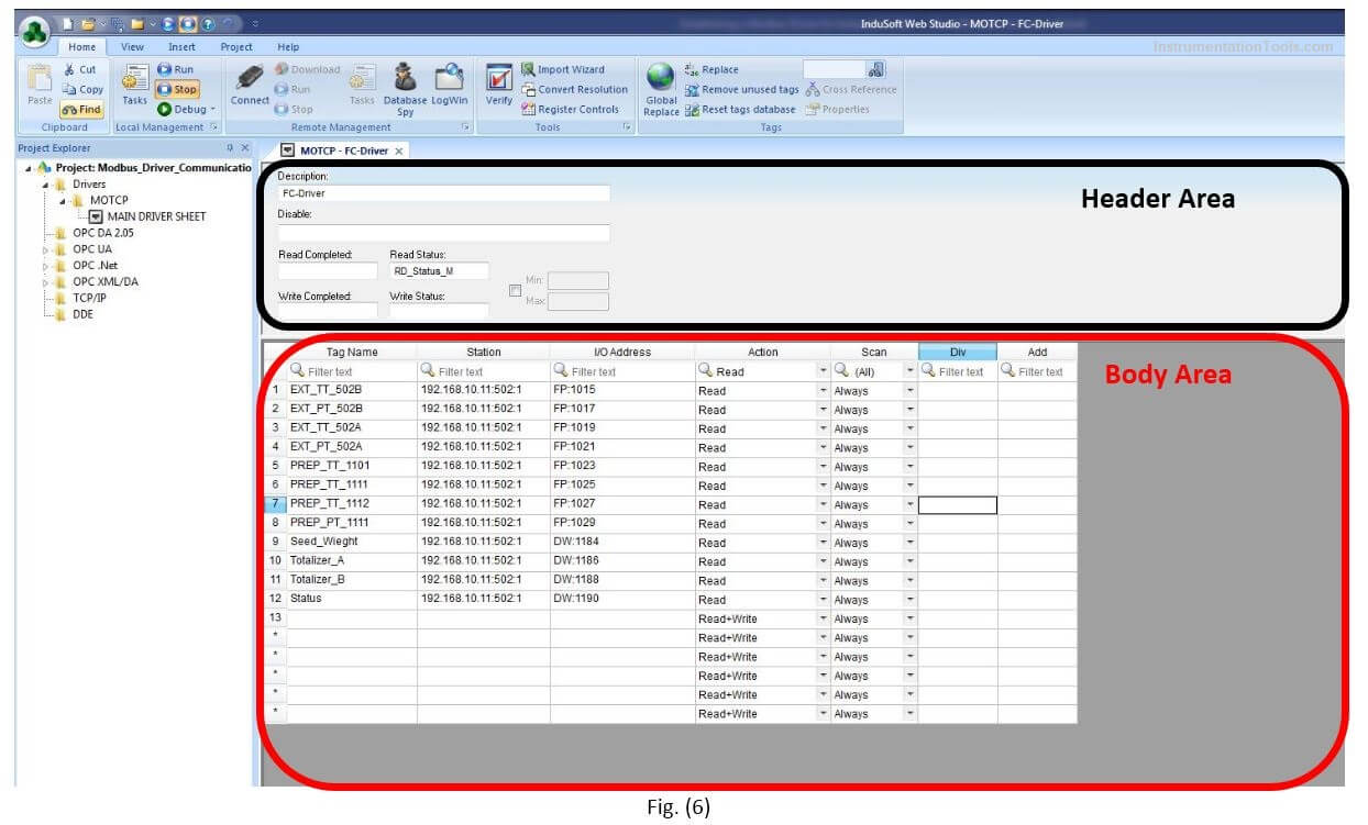
The MAIN DRIVER SHEET worksheet is divided into two areas:
- Header area (top section), contains parameters that affect the all tags configured in the Body area of this worksheet; and
- Body area (bottom section), where you define the relationship between tags in the project and their field equipment address.
Use the Header area parameters as follows
Description field: Type a description of the MAIN DRIVER SHEET for documentation purposes.
Disable field: Type a tag or an expression to enable and disable the communication of each MAIN DRIVER SHEET on the fly.
- Type a value (or expression result) that is greater than zero to disable the MAIN DRIVER SHEET.
- Type a zero (or leave this field blank) to enable the MAIN DRIVER SHEET.
Read Completed field: Type in a tag and the communication driver toggles the tag when it completes a read command.
Read Status field: Type in a tag, which is updated with the status of the last read command.
Write Completed field: Type in a tag and the communication driver toggles the tag when it completes a write command.
Write Status field: Type in a tag, which is updated with the status of the last write command.
Min and Max checkbox: Click (check) to specify minimum and maximum values for data from the field equipment.
Min and Max fields (become active only when you enable the Min and Max checkbox): Type a range of values, which can be converted into an engineering format.
Use the Body area parameters as follows
Tag Name field: Type the name of a project tag to be used by the communication driver.
Station field: Type the number of the equipment station within the network. The syntax in this field varies with each communication driver.
If you’ve configured the driver to do serial encapsulation via TCP/IP or UDP/IP, then the station may be specified using the following format “IP_address: port_number: station”
I/O Address field: Type the address of the field equipment related to the project tag. The syntax in this field varies with each communication driver. Refer to the appropriate driver’s documentation for further information.
Action field: Specify the communication direction, using one of the following options:
- Read (the project continuously reads the address from the field device and updates the Tag value.)
- Write (the project writes the tag value to the field device when the tag value changes.)
- Read+Write (Combines the procedures of both the Read and Write parameters.)
Scan field: Specify the condition under which the tag value is read from the remote device or server and then updated in the project database, using one of the following options:
- Always means the tag is read and updated during every scan of the communication worksheet, regardless of whether the tag is used in any other project screens, scripts, or worksheets.
This option is recommended for tags that must be continuously monitored in the background, such as tags that trigger alarms, tags used in recipes, tags that are recorded in the historical database, and so on.
- Screen means the tag is read and updated only if it is being used in at least one open project screen, either locally or on another client station.
This option is recommended for tags that are used in screen objects, because the project may not need to update tags that are not being visualized anywhere. Selecting this option can improve project performance.
- Auto means the project will automatically choose either Always or Screen, depending on where the tag is used in your project. If the tag is only used in a screen object on a project screen, then the scan will default to Screen. But if the tag is configured in any other interface (e.g., Script, Math, Alarm, Trend, Recipe, Report, Scheduler), then the scan will switch to Always and remain there until the project is stopped.
NOTE
If you are not sure of which option to select, select Always. This will guarantee the tag is read and updated.
If you liked this article, then please subscribe to our YouTube Channel for Electrical, Electronics, Instrumentation, PLC, and SCADA video tutorials.
You can also follow us on Facebook and Twitter to receive daily updates.
Read Next:
- What is a Wet Contact?
- Preventive Maintenance of VFD
- Why 24 Volts DC Power Supply?
- Commissioning and Testing of PLC
- Automation Engineer Troubleshooting