Inst ToolsInst ToolsInst Tools
  • Courses
  • Automation
    • PLC
    • Control System
    • Safety System
    • Communication
    • Fire & Gas System
  • Instrumentation
    • Design
    • Pressure
    • Temperature
    • Flow
    • Level
    • Vibration
    • Analyzer
    • Control Valve
    • Switch
    • Calibration
    • Erection & Commissioning
  • Interview
    • Instrumentation
    • Electrical
    • Electronics
    • Practical
  • Q&A
    • Instrumentation
    • Control System
    • Electrical
    • Electronics
    • Analog Electronics
    • Digital Electronics
    • Power Electronics
    • Microprocessor
  • Request
Search
  • Books
  • Software
  • Projects
  • Process
  • Tools
  • Basics
  • Formula
  • Power Plant
  • Root Cause Analysis
  • Electrical Basics
  • Animation
  • Standards
  • 4-20 mA Course
  • Siemens PLC Course
Reading: What is a Wet Contact? – Basics of PLC Wiring
Share
Notification Show More
Font ResizerAa
Inst ToolsInst Tools
Font ResizerAa
  • Courses
  • Design
  • PLC
  • Interview
  • Control System
Search
  • Courses
  • Automation
    • PLC
    • Control System
    • Safety System
    • Communication
    • Fire & Gas System
  • Instrumentation
    • Design
    • Pressure
    • Temperature
    • Flow
    • Level
    • Vibration
    • Analyzer
    • Control Valve
    • Switch
    • Calibration
    • Erection & Commissioning
  • Interview
    • Instrumentation
    • Electrical
    • Electronics
    • Practical
  • Q&A
    • Instrumentation
    • Control System
    • Electrical
    • Electronics
    • Analog Electronics
    • Digital Electronics
    • Power Electronics
    • Microprocessor
  • Request
Follow US
All rights reserved. Reproduction in whole or in part without written permission is prohibited.
Inst Tools > Blog > PLC Tutorials > What is a Wet Contact? – Basics of PLC Wiring

What is a Wet Contact? – Basics of PLC Wiring

In this article, we will understand what is a wet contact, example sensor wiring in a PLC, advantages and disadvantages.

Last updated: September 28, 2022 4:09 pm
Viral Nagda
PLC Tutorials
1 Comment
Share
4 Min Read
SHARE

In this post, we will understand the concept of a wet contact in PLC and understand its wiring.
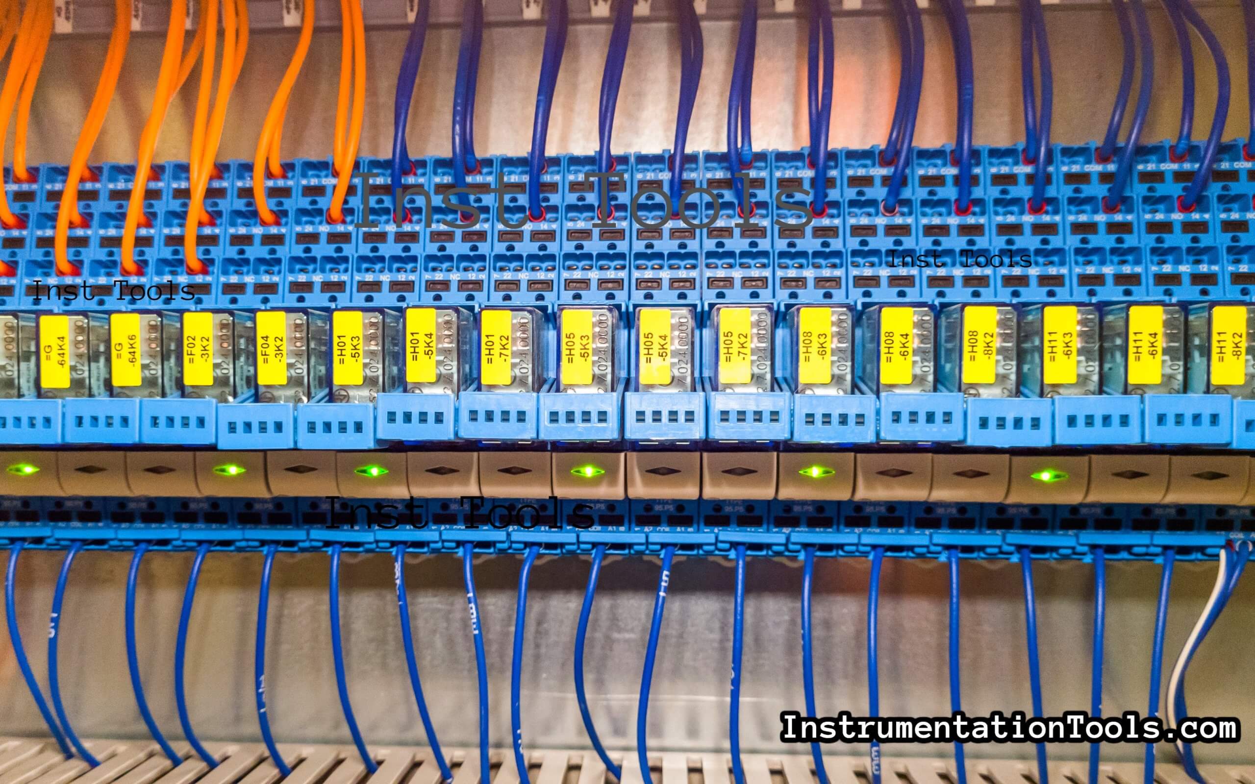
Contents
PLC WiringTypes of ContactsWhat is a Wet Contact?Sensor Example WiringDisadvantages of Wet ContactAdvantages of Wet Contact

PLC Wiring

In PLC electrical wiring, understanding the concept of contact switching and wiring is important for operation.

A circuit is completed when the contact is closed; so, it is important to understand the wiring and switching.

What is a Wet Contact in PLC

Types of Contacts

When it comes to contact wiring, basically, two types of contacts are used

  1. Dry Contact
  2. Wet Contact

It is important to note that it applies only to digital inputs and outputs; because analog is variable in nature and there is no concept of contact in it.

In this post, we will understand the concept of wet contact wiring in a PLC.

What is a Wet Contact?

We will learn about wet contact with a simple example of a sensor. The sensor has a contact that when energized, gives the output according to the object sensed.

The contact is to be given the same potential as the potential given for powering the sensor. If the sensor senses an object, then the output of the contact turns on and if the sensor does not sense the object, then the output of the contact turns off.

This means the contacts and switching are powering the circuit with the same potential as at its source. So, a wet contact is defined as a contact that is powered by the same power source used by the control circuit to change the contact.

In the example we discussed here, the circuit power is supplied by the switch; it is not using any other external power source for the contacts. If it was to be supplied by another power source, then the contact potential could have been different than the voltage which is applied as power for the sensor.

Sensor Example Wiring

Let us simplify it more for better understanding. A sensor has 3 basic terminals – positive potential, negative potential, and output.

The positive and negative potential is used to energize the sensor. The contact circuit is not isolated from the power circuit.

When the sensor is energized, it checks the sensing internally. If the object is sensed, then the black line output as shown below figure turns ON (the output is positive in nature) and turns ON the load as negative potential is already present at it.

When the object is not sensed, then the output of the sensor turns OFF; which in turn switches OFF the load.

Wet Contact

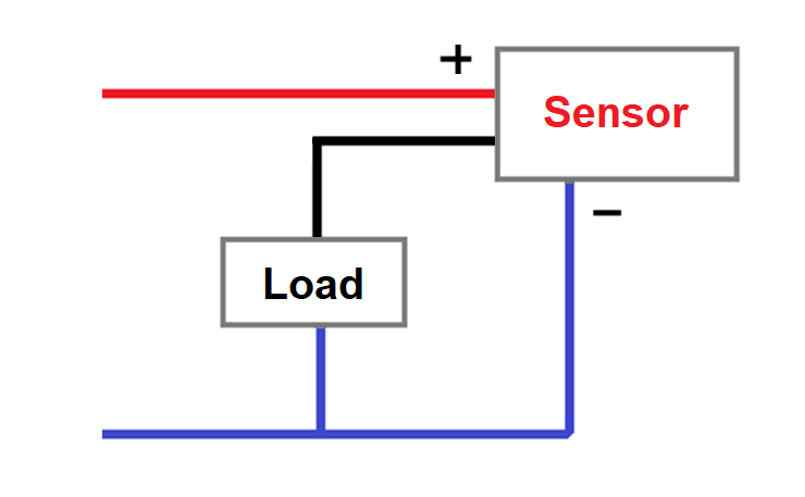
This shows that a wet contact acts just like a switch, which when powered, supplies the same switching action (with the same power) to the load device.

Disadvantages of Wet Contact

They cannot provide isolation between two circuits. Both the input and output circuits are inter-dependent.

Advantages of Wet Contact

But, one main advantage is the simplicity of wiring in these types of contacts. There is less wiring in it and you don’t have to look much into it.

Power consumption becomes less and all your automated wiring comes in the same potential, which makes it look easy; though difficult to isolate.

In this way, we understood the basic concept and wiring of a wet contact in PLC.

If you liked this article, then please subscribe to our YouTube Channel for Electrical, Electronics, Instrumentation, PLC, and SCADA video tutorials.

You can also follow us on Facebook and Twitter to receive daily updates.

Read Next:

  • PLC Wiring Diagrams
  • Electrical Wiring Diagram
  • 4-20 mA Transmitter Wiring
  • Why 24 Volts DC Power Supply?
  • Interposing Relay Panel Wiring
Don't Miss Our Updates
Be the first to get exclusive content straight to your email.
We promise not to spam you. You can unsubscribe at any time.
Invalid email address
You've successfully subscribed !

Continue Reading

Mitsubishi Electric GOC Controllers
Light ON OFF Control using PLC
SCADA System Vulnerabilities
Applications of SCADA
Types of Limit Switches – Principle, Advantages, Disadvantages
Why Baud Rate is Important in Modbus Network?
Share This Article
Facebook Whatsapp Whatsapp LinkedIn Copy Link
Share
1 Comment
  • Messomo says:
    September 14, 2022 at 3:44 pm

    I have appreciate this publication. I am the student engineer in robotics industrial from Cameroon in Africa so l am very build for this post. Thank you

    Reply

Leave a Reply Cancel reply

Your email address will not be published. Required fields are marked *

Stay Connected

128.3kFollowersLike
69.1kFollowersFollow
210kSubscribersSubscribe
38kFollowersFollow

Categories

Explore More

How to Download EcoStruxure Machine Expert? Schneider PLC Software
What are Functions in PLC Programming? (FCs)
PLC Counter Instructions
Troubleshoot the Status of a PLC Via CPU Indicators
PLC Program with 2 Toggle Switches and 4 Motors
D Flip Flop PLC Ladder Logic
PLC Programming Example on Multi-Motor Control for Beginners
SCADA and HMI Systems – Differences, Similarities, Purpose

Keep Learning

PLC Memory Mapping

PLC Memory Mapping and I/O addressing

Structured Text PLC Example for Motor Interlocking and Control

Structured Text PLC Example for Motor Interlocking and Control

Key Facts About RS485 Industrial Network

Key Facts About RS485 Industrial Network

JMP instruction in PLC Programming

How to use JUMP Instruction in PLC Ladder Logic?

Timer-based vacuum cleaner in Schneider PLC

Schneider Electric PLC Timer Problem: Vacuum Cleaner

Control of Double-acting Pneumatic Cylinder

Ladder Logic for Control of Double-acting Pneumatic Cylinder

Best PLC for Your Project

Finding the Best PLC for Your Project – Tips and Tricks

Siemens Process Mode

Test and Process Modes in Siemens PLC

Learn More

Sheet Metal Fabrication Manufacturing and Design

Ideal Guide To Sheet Metal Fabrication Manufacturing and Design

PLC-based mail box automation

PLC Program for Mailbox with Letter Counting & Light Indicators

Ceramic Bearings

Everything You Need to Know About Ceramic Bearings

Time Response Analysis

State Variable Analysis – Part I

Rate of Rise Thermal Detectors Working Principle

Rate of Rise Thermal Detectors Working Principle

Transistor as an Amplifier in Common Emitter

Transistor as an Amplifier in Common Emitter

Power Electronics Objective Questions

Force Commutated Inverters Objective Questions

HMI

Learn about SCADA and HMI Systems

Menu

  • About
  • Privacy Policy
  • Copyright

Quick Links

  • Learn PLC
  • Helping Hand
  • Part Time Job

YouTube Subscribe

Follow US
All rights reserved. Reproduction in whole or in part without written permission is prohibited.
Welcome Back!

Sign in to your account

Username or Email Address
Password

Lost your password?