Let’s study the working of pulse timer instruction in Siemens PLC programming.
Pulse Timer in PLC

Block Description
Pulse Timer:
When Timer receives positive pulse at the set input (S), it enables the Q output as long as the preset value set for the timer. The signal change is necessary in order to enable the timer.
Timer will run as long as the input sign (S) at “1” or accumulator value reaches preset value. The signal state at the output (Q) is at “1” as long as the timer is running. If input (S) changed from “1 to 0” before the time interval has elapsed, timer stopped along with disabling output (Q).
The timer reset input enables to reset the timer while it’s running. Accumulator value backs to zero. Accumulator value can be read at the BI and BCD output of the timer.
Pulse Extended Timer:
When Timer receives positive pulse at the set input (S), it enables the Q output as long as the preset value set for the timer. The signal change is necessary in order to enable the timer.
The signal state at the output (Q) is at “1” as long as the timer is running. If input (S) changed from “1 to 0” before the time interval has elapsed, timer continue to run and enables output (Q) till accumulator value reach preset value.
The timer reset input enables to reset the timer while it’s running. Accumulator value backs to zero. Accumulator value can be read at the BI and BCD output of the timer.
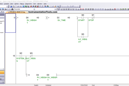
Ladder Logic
Case 1: When Input set (S) goes ON for the first time

Network 1:
Input I0.0 is pressed, it gives positive pulse to S input of timer (T0) which makes timer to start running upto 20s ,the time mentioned in the preset value(TV=ST#20s).Output (Q0.0) of timer (T0) enable for 20 s.
Network 2:
Input I0.2 is pressed, it gives positive pulse to S input of timer (T1) which makes timer to start running upto 20s,the time mentioned in the preset value (TV=ST#20s).Output (Q0.1 )of timer (T1) enable for 20 s.
Case 2: When Input set (S) goes OFF before time interval (20s) get elapsed

Network 1:
Input (I0.0) to the timer (T0) is turned off before the time interval elapsed will make the timer to stop running and output (Q0.0) to go off.
Network 2:
Input (I0.2) to the timer (T1) is turned off before the time interval elapsed will make the timer to continue running and output (Q0.1) to remain ON till the time interval has elapsed.
Case 3: When Reset input (R) goes ON before time interval (20s) get elapsed
")
Network 1:
Reset Input (I0.1) to the timer (T0) is pressed; timer stopped running and disables the output (Q0.0).
Network 2:
Reset Input (I0.3) to the timer (T1) is pressed; timer stopped running and disables the output (Q0.1).
Author: Hema Sundaresan
If you liked this article, then please subscribe to our YouTube Channel for PLC and SCADA video tutorials.
You can also follow us on Facebook and Twitter to receive daily updates.
Read Next:
- Motor control in Ladder logic
- Conveyor Ladder Logic Program
- Function Block Programming
- Operator Interface for SCADA
- Control Instructions in PLC


Hi,Mdm
Thank u for a example .its very helpful for me to use ur instruction in my project