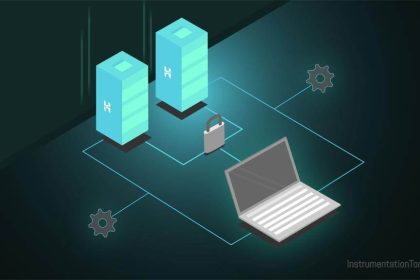
Process Control Systems Philosophy is a cloud environment that is the basis of all I&C-Team Documentations and Activities (Including Systems Architecture), and the main design configurations in such environment will specify the required systems (and relevant Instrumentations) and their requirements/ specifications in Process Plant Project.
In this article, we try to review some suggested subject examples which can be considered as main (advised) concerns (30 Items) for studying in developing Process Control Systems Philosophy.
30 Concerns for Control System Philosophy
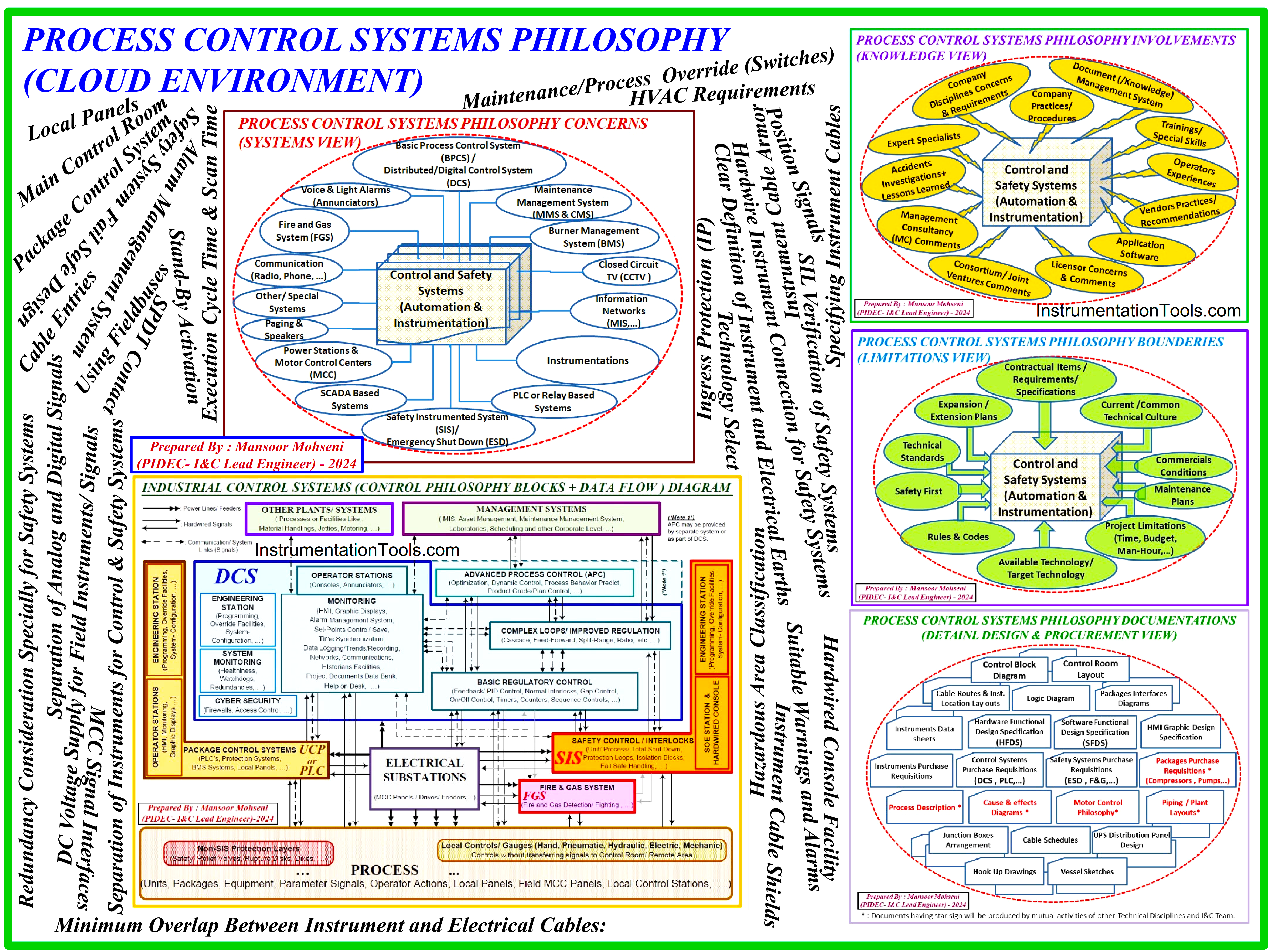
Figure-1: Process Control Systems Philosophy as Claud Environment
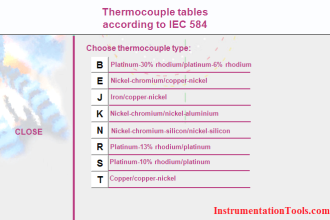
1. Technology Select
The Instrumentation and Control (I&C) Team shall know the available and possible technologies which shall be used in the Process Plant Project and select the best options for satisfying project requirements.
This item may include: conventional Systems (4 to 20 mA or 0 to 10 VDC from different available voltage and current levels), HART Facility, Foundation Fieldbus, Profibus, Modbus, … , and the proper collection or configuration of such options in any system. This concern is highly dependent on project requirements reflected in the project contract and its attachments.
I&C-Team shall use the simpler and more reliable instrumentation technologies for Safety Instrumented Systems and relevant loops, while for reaching to the best target SIL, the maximum and usual SIL Certification of available technologies shall be known.
2. Package Control System
The I&C Team shall investigate suitable methods for applying safety and control systems for each package inside the Process Plant Project.
Generally, three methods may be applied for Package Control and Safety Systems:
- Completely implemented in plant DCS (Distributed/ Digital Control System) and SIS/ ESD (Emergency Shut Down) System.
- Using separate dedicated control and safety systems (cabinets or panels) as UCP/ PLC Panel (Unit Control Panel/ Programmable Logic Controller Panel).
- Implementing required control and safety requirements by the combination of DCS/ ESD and UCP for different required functionalities.
Selecting the best and actual method for each package depends on different factors and conditions existing in each project (some of such factors and conditions applied to package control systems and selecting suitable system arrangement method are studied in separate article).
3. Separation of Instruments for Control & Safety Systems
To guarantee the exact operation of Safety Instrumented Systems, it is asked to consider each instrument connected to just one dedicated system (DCS or ESD) for any relevant action.
In some projects, which are using several instruments at a single point (like 2 out of 3 arrangements) I&C-Team may consider some overlaps for instrument usage by project acceptances (some of the instruments connected to both DCS and ESD). However, in each project, the I&C-Team shall study such subjects and specify the accepted routine for the connection of instruments to target systems.
4. Hardwire Instrument Connection for Safety Systems
Usually, it is recommended to consider any safety action in the SIS to be executed based on Hardwired connection signals, but such execution based on communication link signals are limited to special cases like RESET functional facility requests.
Nowadays, the decision on this subject is very important for signal interfacings between DCS and ESD systems, since some vendors offer DCS and ESD systems as the integrated platforms (and they guarantee the highest reliability for communication networks connecting these systems) which is a big challenge for changing these signals as a communication link.
For a large number of DCS and ESD Interfacing signals accepting communication link signals may have great effects on systems (hardware) sizes and actual savings for space and money.
5. SIL Verification of Safety Systems
It is recommended that the Safety System to be considered as the maximum available SIL Level at the beginning of the project (i.e. SIL-3 for most of the Process Plant Projects) since by which, reaching the target SIL for all SIF Loops may be accessible as default (from point of system view). In fact considering Safety System as SIL-3 is necessary for reaching SIL-3 safety Loops, but it is not sufficient for guarantee reaching the target SIL.
On the other hand, after this consideration, after the SIL Study, reaching the SIL Targets for different loops will depend on the instrument’s SIL Level. If for some safety loops, the Target SIL cannot be achieved, then the selected instruments or their arrangement (possibly the number of instruments) are to be changed, and such changes may cause commercial challenges between the client and the designer team. By considering a Safety System with a high SIL Level, such explained challenges may be quite limited.
6. Redundancy Consideration Especially for Safety Systems
Redundancy considerations for hardware components of loops may have great effects on Process Plant availability requirements (especially for Spurious Faults/ Failures).
It shall be noted that without Redundancy considerations, any spurious fault/ failure of the subject component may trip or stop the process plant, and this case may force big damages to plant productions.
Usually, Redundancy can be defined for components such as CPU (Central Processing Unit), Input-Output (I/O) Cards, Power Supply Units, Communication Links/ Networks, Installed Instruments …
In Process Plants like Oil& Gas and Petrochemical Plants, it is customary to consider at least a redundancy facility for CPU and Power supplies of both DCS and ESD, while other components are suggested to be considered in redundant mode for all safety (ESD) and closed circuit Analog Loops (Some Analog I/O’s inside DCS).
7. Execution Cycle Time & Scan Time
In most Process Plants the Safety Loops shall be activated as soon as possible and so the Execution Cycle Time & Scan Time of hardware and software facilities used in Safety Systems (SIS) shall be studied and verified by the I&C-Team (to guarantee some minimum times).
Accordingly in DCS and Package PLC Control and Interlock Loops there are some critical cases that shall be studied for finding such minimum times requirements (such as Anti-Surge Control Loops).
However, for other normal cases loops, the I&C-Team shall investigate the systems for doing such loops with logical times (which couldn’t produce any problems for the continuity of processes in the plant).
8. Hardwired Console Facility
For controlling some process control & safety loops, the process control operators shall do some activities quickly, and in these cases, they need some hardware facilities.
Although such similar facilities may be implemented in graphic pages of HMI Monitors (consoles), but it is clear that operators can do such activities more quick (on some limited cases) by using a Hardwired Console (than HMI graphics which may need some times for navigate to the proper page and finding the action points).
For example, in most Process Plants usually for activation of some Emergency Trip actions, some Emergency Push Buttons are considered on Hardwired Console. Activation of Stand-By equipment, and isolating the process routes are some other examples for need of some hardwired switches on the Hardwired Console.
9. Local Panels
Considering some Local Panels for executing some actions in the field (process site) is a usual concept in most Process Plants.
Such Local Panels may be used in different modes such as:
- Process/ Unit/ Equipment Start-Up which needs some field operator investigations and activating the subject by complete field care intentionally.
- Selecting the physical facilities or routes or sequences for Process/ Unit/ Equipment by investigating the field actual conditions.
- Executing Maintenance activities and doing or implementing some physical tests on Process/ Unit/ equipment.
Interactions of Local Panels with Process/ Unit/ Equipment Logics and Interlocks (Automatic Commands) or Control Room Operators Requests (Remote Commands) for suitable Control & Safety Systems outputs/ commands (and considering the priority of requests) are very critical.
As an example for most of the cases when Local Panels are used in Maintenance mode, all Remote/Auto commands shall be disabled for considering safety of field operators. Considering Local Control Station (LCS) connected directly to MCC circuits (for start/ stop the motors) with hardware activated Local/ Remote Switch facility (in MCC circuits and regardless of Control & Safety Systems logic programs) is due to this concept.
For considering another example, we may notice to the limited cases which are occurred in Emergency conditions that Local Panel requests shall be disabled. For example during Turbine/ Compressor Shutdown, field operators don’t have permit to switch of Lube Oil Circulating Pump (System logic output will have more priority than Local panel request).
Another important consideration for Local Panels are related to care for scope of actions and sequence of doing activities during the time or operations, since by such consideration, I&C-Team shall care for installing some suitable switches or keys for activation permits at right time (further to suitable logics and timers inside control & Safety Systems).
Generally I&C-Team shall coordinate with all responsible teams (especially Process and Operation teams) to find right suitable concept for each Local Panel existed in Process Plant.
10. Stand-By Activation
Selecting and Activation of Stand-By Process/ Unit/ Equipment via manual (process operator) or automatic (logic outputs due to process parameters) with considering priorities and possible permits (for Local or Remote) is another important item.
Also in some cases, the sequence of returning to the previous case (with reaching to normal condition) or even automatic cycle change may be the possible cases which shall be considered. However, choosing simultaneous running of the same items or switching off the extra item(s) is an important concern.
When the Stand-By subject is more than one, selecting the right item (from extra possible options) and the possibility of running simultaneous items will be more important.
I&C-Team shall investigate and review all possible cases in the Process Plant and define some (limited) typical configurations which can be assigned for all existing ones in the project.
11. Suitable Warnings and Alarms
Provision of suitable warnings and alarms for process operators (in control room or in the plant field/ site) on abnormal conditions by using (audible or visible) facilities (such as horns, sirens, lights, beacons, …) with the proper sequence of activation/ reset functions is a very important concern.
The sequence of activation of audible/ visible facilities in the control room shall be developed in conjunction with alarms appearing on operator workstations (consoles) too. I&C-Team shall review the matter exactly with the help of other technical disciplines (such as Process, Operation, and Safety Teams) to implement the best philosophy.
12. Alarm Management System
An alarm Management System shall be implemented for announcing suitable alarm appearance (text and color) with proper sequence of appearance and vanishing and saving on the project database.
Alarm Management facilities shall be used suitably to appear optimum alarm list for operators while all alarms saved for future tracings and event studies. Furthermore, the I&C-Team shall provide a “First-in Initiator Record” philosophy for quickly informing the process operators in the case of activation of safety interlocks for better quick actions.
13. Safety System Fail-Safe Design
Considering Fail Safe Concept for safety loops or safety systems, will help process plant end users to have better and quick actions in the case of instrument or relevant connection cable failures.
In fact, by such concept consideration, Process Plant operation will have the guarantee to have suitable actions on abnormal process conditions (safety loop cases), because the upset conditions will be detected by good reliability.
Notice that if Fail Safe concept is not used in the design philosophy, then if during the normal conditions of processes, the instrument contact has a failure or the connection cable is damaged, the process operators will not be informed, and in the case of occurrences of bad (upset) conditions of the processes, safety systems will not have right actions.
If the Fail-Safe concept is not considered for safety loops or systems, then compensation arrangements such as Line Fault (LFT) Monitoring shall be used. For example, Fire & Gas Systems (FGS) usually is implemented by a line Fault Monitoring arrangement.
14. SPDT Contact
For switch-type instruments (like pressure or level switches) which shall have normal contact, considering SPDT (Single Pole Double Through) type contact will make more flexibility for signal defining or extra signal transferring (two signals transfer with negate function). Also, such a facility easily helps us with the use of switches either as Normal-Open (NO) or as Normal Close (NC) on process conditions.
Such SPDT contact consideration may be applicable for signals between two systems (which are usually the relay outputs) too.
15. DC Voltage Supply for Field Instruments/ Signals
Now a days it is very usual to consider (low) DC Power Supplies for feeding instruments and signals due to the safety of operation. However, there are different levels of DC voltages have been considered as standard levels for such power supplies.
It is recommended to consider one level as standard level of DC voltage in whole the process plant in order to minimize the possibility of any future problems for transferring the signals or damaging the instruments. As an example usually designers choose 24 VDC as standard level of voltages for instruments and signals.
Although selecting one standard low level of DC voltage is a good practice for minimizing the probable problems, but it should be noted that such considerations for long distances wiring or for high power consumption instruments may cause big problems, since in such cases for guarantee the validity of transferring signal or power we shall need wires with big cross-section area to compensate drop of a voltage level (and in some cases, it is not possible or it will be illegal).
In order to solve this problem it would be better to define two standard levels of voltages (one Low level and the other one High Level). For example, considering Low Level voltage for Instrumentations can be 24 VDC, while the Higher level can be UPS Power Feeder or even Mains Power Feeder (i.e. 110 or 220 Volts AC).
16. Clear Definition of Instrument and Electrical Earths
In Process Plants, usually there are two main (different) sets of earth connections are defined and are available: Electrical Earth and Instrument Earth (which is usual in some process plants to call (wrongly) them as Dirty and Clean Earths).
First of all, it shall be mentioned that based on real situations and also according to default considerations in all Electrical and Electronic standards we have just one earth, but instead, we may have different paths to reaching the earth.
In fact earth connection may be implemented by provision of several earth pits (or wells) with the network (or mesh) connection of these pits, for different Instrument or Electrical earth paths.
Since Instrument Earth paths are used for transferring low-level signals (noises) the required earth impedance (resistance) shall be much lower than those which is required to Electrical Earth. In practice, by increasing the number of earth pits (wells) and the quality of material surface connection to earth (in the wells or pits) and also by using better mesh or network (or even more cross-section size of source termination cable) it is possible to provide lower resistance earth connection.
1 and 10 are commonly considered Earth Resistance values for Instrument and Electrical earths at Process Plant Projects. It shall be mentioned that the considered wells and pits networks for Electrical and Instrument Earths are connected to each other (at wells heads connections) but the considered paths to Electrical and Instrument Systems shall be completely separate.
On the other hand, if the different Electrical and instrument paths are disconnected from earth wells, then they shall be completely isolate from each other (and the resistance between these two paths shall be infinity).
Electrical Earth:
Simply the Electrical Earth for process plants is required for:
- Balancing the power transfer system (phases) and making base reference
- Protecting the human and equipment from electrical connection leakage or shock. On the other hand all metallic surfaces of equipment and structures shall be connected to Electrical Earth for safety view (so sometimes this earth is called as Protection Earth (PE) or Primary Earth (PE)).
- Protecting the plant area and specially structures from Lightening crushes.
- Protecting the equipment and preventing the accident potential of fire or explosion due to static electricity discharge.
Instrument Earth:
Simply the Instrument Earth for process plants are needed for:
- Transferring the noise or disturbance signals to the earth for guarantee validity of subject (main) signals. Since this earth path is used for Instrumentations, usually it is called as IE (Instrument Earth).
- Making common zero reference base for all DC voltages of different systems used in the process plants (DCS, ESD, PLC, UCP,…). Since this earth path is used for making equipotential levels for different systems, usually it is called as SE (System Earth).
- Making common zero floating reference for Zener Barriers which are used for Intrinsic Safety instrument circuits. So usually it is called as ISE (Intrinsic Safety Earth). Now a days instead of Zener Barriers, Galvanic Isolator Barriers are used which don’t need any separate Earth path.
It is repeated that all Instrument Earth Paths will be connected to Considered Instrument Earth Pits (Wells) Network and all Electrical Earth Paths will be connected to Considered Electrical Earth Pits (wells) Network, and the Instrument Earth Paths are isolated from Electrical Earth Paths, but they will be connected to each other at head of both Earth Wells Networks. By explained configuration we can say we will have one Earth (source) for all Instrument and Electrical Earth requirements, but the paths to reach this source will be different.
17. Separation of Analog and Digital Signals
For providing maximum protection on signal interferences and (hence preventing disturbances or noises and) having valid signals (especially for Analog ones) it would be better to transmit Analog and Digital signals to the systems (or between the systems) via separate connection cables.
By following this concept, we shall consider separate Junction Boxes (JB’s) or Terminal Blocks in common JB for analog and digital instruments (or signals), while using separate multi-cores or multi-pairs cables to dedicated terminal blocks in the target (marshalling) system.
18. Instrument Cable Shields
In order to guarantee the validity of transferred signals, it is advised to consider all Instrument Cables to be equipped with suitable shield (screen) facility.
However for Instrument Multi-pairs Cables, it would be better to equip such cables with both shield (screen) for each pair further to overall cable shield (screen). It shall be noticed that for usability of such shield (screen) it shall be connected to Instrument Earth (IE) just from system side (for cables between different systems it shall be connected to Instrument earth just from one system).
19. Instrument Cable Armor
Since the field/ site of Process Plant Projects (such as Oil & Gas, Petrochemical, …) include possibility of mechanical damages forced to field Instrument Cables, It is advised to equip such cables with armor facility.
However this (metallic) armor shall be connected to Electrical Protection Earth (PE). By this connection the cables will be protected against accidentally connections (along the cable route) to electric lines.
Furthermore if such cables installed in area which have possibility of lightening shock, the big amount of induced electrical energy will be transferred to Protection Earth (PE) too, and hence protects the instrumentation systems from such possible shock.
20. Minimum Overlap Between Instrument and Electrical Cables
It is advised to consider Instrument Cables routes to be designed with minimum overlaps with Electrical Power Cables routes (such as motors cables) to minimize the unwanted induced voltages or currents on Instrument Cables.
On the other hand, the routes of Instrument and Electrical Cables shall be design to be minimum parallel and crossover with each other’s. However if in some cases there is no possible solution, then it is advised to use isolation sheets (with some distance margins) between the two cable types.
Using isolation sheets (with some distance margins) and making orthogonal cross over (instead of parallel) will have great effects on minimizing unwanted induced power.
21. Specifying Instrument Cables
For Process Plant Project, I&C-Team shall investigate the required cable types as singles or Multi-Cores or Multi-pares and specify the best limited types.
As an example, they may specify such cables as single pair, 3-pairs, 5-pairs, 10-pairs, 20-pairs. In another project, I&C-Team (due to project conditions) may select the different number of pairs or even may use Multi-Cores cables instead of Multi-pairs cables.
However, they shall provide exact data and specifications for these cables such as: core cross-sectional size, number of cores or pairs, shield (screen) and armor facilities, material of cable cover and isolation sheets, etc.
However the considered arrangement for transferring digital signals (two cores or one pair per each signal or transferring different signals by single core per each signal further to an extra common core) will identify multi-core or multi-pairs cables selection.
22. Hazardous Area Classification
I&C-Team shall study the process plant area for different possible Hazardous Areas and investigate for defining suitable configurations for protection codes of Instruments and Systems. They shall have enough care for considering suitable Isolation Barriers in relevant systems.
Identifying data and specifications shall be done based on project requirements especially for fixing single channel barriers or accepting multi-channel types. Power feeding to barriers (through rail or separate feeding) may be some options to be decided.
Since some of these isolation barriers may be used in Safety Systems, so the required SIL level of such items further to match with some special case signals (such as NAMUR signals) shall be noticed by I&C-Team too.
23. Ingress Protection (IP)
I&C-Team shall have enough care for selecting Instruments and Systems due to installation area and required protections for dust or moisture. Usually in Process Plant Projects (Oil & Gas and Petrochemical,…)
IP-65 is considered as the minimum default value for Instruments or systems located in the project field/ site, while for those installed in buildings, it shall be studied and then decided (as an example for panels or cabinets installed in the Control Building, it is usual to consider IP-41 or IP-42).
24. Main Control Room
The main or Central Control Room (CCR) for Process Plant Projects shall be studied and investigated from different sides/ conditions and requirements for designing the best location, arrangement, and specifications.
As an example during such a study, the location of CCR shall be selected in the best position (may be in the center of the plant) to have optimum distances for all required cablings (as much as possible).
Since the CCR may be located in a Hazardous Area, Blast Protected type building shall be considered in this case. However, the direction of wind for transferring probable toxic (or even flammable or explosive) gases shall be considered for suitable building entrance sides.
Further to physical process requirements, CCR shall be investigated by Functional Operations too for considering suitable rooms and spaces and arrangements, to have the best access ways for operators, supervisors, and all responsible persons.
25. HVAC Requirements
I&C-Team shall have enough care for considering suitable HVAC requirements in all relevant rooms in the Control Building, especially for Operator Rooms and Axially (Panels or Cabinets) Rooms.
They shall have close coordination with responsible discipline to provide separate settings for different areas which contain human or cabinets/ panels, since their requirements are completely different. This item will have more importance in the case of using just one HVAC system for whole control building.
For cabinets or Panels which are installed at the project field/ site (outside the buildings), heat dissipation is a very critical point, since natural ventilation may be not enough for such panels and may require additional equipment. Due to the possibility of the existence of flammable or explosive gases at the project field/ site, such cabinets or panels shall be equipped with some special ventilation such as vortex coolers.
On the other hand, project field/ site ventilation required for heat dissipation is a complex problem and shall be exactly investigated by I&C-Team on possible cases.
26. Maintenance/Process Override (Switches)
For compensating faulty instruments/ signals (up to changing such instruments or repairing them) and preventing the trip condition force on the process operation of the plant, usually, process operators need some facilities for overriding such signals on special conditions. Such facilities can be achieved by activating some permit switches which are called Maintenance Override Switches (MOS).
The conditions and procedure of such activation and monitoring and announcing the required (high level) alarms and also making the validity of such switches during the time shall be defined and configured (in Logic) exactly.
Similarly, for some special process cases or even during the process start-up, process operators may need similar facilities like MOS which are implemented accordingly by I&C-Team as Process Override Switches (POS).
27. Using Fieldbuses
The acceptable fieldbuses in different project systems shall be investigated on the correct implementation of such buses especially due to distances of signals (and relevant cable lengths) which shall be monitored continuously by the I&C-Team up to reaching the end of design.
As an example for spur and trunk lengths of Foundation Fieldbus signals, the I&C-Team shall have exact cares.
28. Cable Entries
I&C-Team shall define the acceptable list of standard cable entries (cable glands sizes and types) due to project conditions and specified Instrument cables.
For Process Plant Projects, it is recommended to don’t consider cable entries to the panels or cabinets from upside, due to risk of water, liquid (or rain) leakage to the panel. In fact cable entries from bottom of the panel or cabinet is the best option.
29. Position Signals
Due to minimizing mechanical damages to position (status) instruments, during the mechanical movements, it would be better to select Non-Contact mentioned instruments.
For example, for position feedback signals of valve status, it is advised to consider Proximity Switches instead of mechanical/ limit switches.
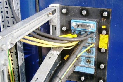
30. MCC Signal Interfaces
With close coordination with project PROCESS and ELECTRICAL Teams, the interfacing signals between MCC (Motor Control Center) and Process Control & Safety Systems shall be defined as standard typical loops for different possible cases.
However close coordination shall be done with ELECTRICAL-Team for selected philosophy on MCC Signal Interface Termination (MCC-SIT). For more study in this subject, you may refer to articles inside Instrumentationtools.com.
References:
- Process Control Systems Philosophy Concept
- Interactions With Process Control Systems Philosophy
- System architecture and process control systems philosophy
- Instrumentation Design Engineer Roles & Responsibilities