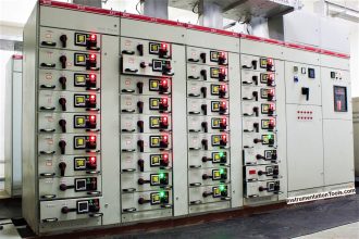
Earthing of electrical systems is required for a number of reasons, principally to ensure the safety of people near the system and to prevent damage to the system itself in the event of a fault.
The function of the protective conductor, or earth, is to provide a low resistance path for fault current so that the circuit protective devices operate rapidly to disconnect the supply.
The NEC, National Electrical Code defines a ground as: “a conducting connection, whether intentional or accidental between an electrical circuit or equipment and the earth, or to some conducting body that serves in place of the earth.”
When talking about grounding it is actually two different subjects, earth grounding and equipment grounding.
Earth grounding is an intentional connection from a circuit conductor usually the neutral to a ground electrode placed in the earth.
Equipment grounding is to ensure that operating equipment within a structure is properly grounded.
These two grounding systems are required to be kept separate except for a connection between the two systems to prevent differences in potential from a possible flashover from a lightning strike.
The purpose of a ground besides the protection of people plants and equipment is to provide a safe path for the dissipation of Fault Currents, Lightning Strikes, Static Discharges, EMI and RFI signals and Interference.
Improper grounding can create a lethal hazard. Correct grounding is essential for correct operation and safety of electrical equipments.
Grounding can solve many problems, but it can also cause new ones. One of the most common problem is called “ground loop”.
Consideration of ground can be very complex and application specific. But in many of these applications, when we make wired connections to ground and to electrical equipment, there are a few rules of thumb that are helpful:
- For isolated power applications where a connection to earth ground is not apparent, ground should be chosen as the common return path from power supply (DC minus). It may be necessary to hard-wire earth ground to this point if an earth ground connection is not already made by the power supply.
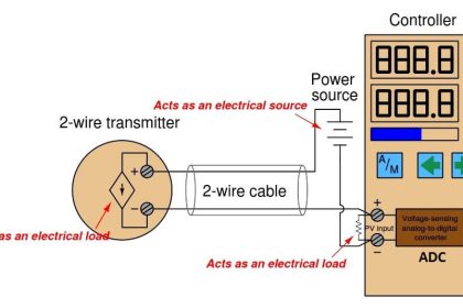
- Do not ground a signal at more than one point. Typically a signal is grounded at its source (including its shield).
- In general, as stated above, we try to never ground a cable at both ends. But one possible exception to this rule is when we are grounding cable shields in small signal applications. For most applications where only small differences in potential exist between grounds at each end of the cable, our equipment will work better when its shield is grounded at each end of the cable (at a minimum, ground it at the end closest to the noise source). Another exception is where your equipment connects to power, as DC powered equipment will often connect earth ground at the power supply minus terminal, but you should additionally include a connection to ground local to the instrument. This is done not only to stabilize applied voltages, but also because internal suppression devices in the instrument need a local, low resistance, low inductance path to shunt potentially destructive energy.
- For EMC purposes, a wired signal between devices should have earth ground applied at the end of the cable nearest the noise source of the signal, or nearest the noisiest device. Failure to provide a path to ground at the “origin” of the noise may result in the cable and/or its shield becoming an antenna for this noise, increasing its power and spread into other areas of the circuit, as well as potentially increasing system emissions.
- Do not use the chassis of the device as the ground conductor (i.e. make only one ground connection to the chassis). Note that many devices are required by code to have a safety ground connection to their metallic chassis or enclosure, but the chassis should never be used as a return path for load current to the device (for “safety” ground, it is sometimes used only as a return path for fault current). Note that the chassis connection to earth ground is sometimes used as the center of a star grounding scheme for the enclosed circuit.
- Many instruments are housed in plastic enclosures and may not make a connection to earth ground via their chassis. These instruments usually rely on direct-wired connections to earth ground at their terminals, as directed in their connection diagrams. In general, signal connections to these devices should be earth grounded at the end of the I/O cable nearest the instrument. This is because the instrument needs a low-impedance/low-inductance path to earth ground locally, to allow its various filters, capacitors, and transient suppression devices to shunt potentially destructive energy to earth ground without being impeded by high levels of inductance and resistance in the path to earth.
- Do not bundle noisy or high-energy signals or power with low level signals. Route all AC power wires away from sensitive signals and signal paths.
- Do not duplicate ground connections to the main power line at different points—try to connect all AC powered devices to the same power outlet when possible and safe. Similarly, use a star-grounding concept when making ground connections to your circuit.
- Do not combine or bundle isolated signals in the same shield or conduit.
- Do not allow conductive material to float unattached to any ground (it should connect to ground at one point).
- Do not leave unused shielded conductors in a bundled cable disconnected from ground. Ground unused conductors of a bundle at the load. In general, ground the cable shield at the signal source (or at both ends).
- Minimize the length and loop area of the wires that break-out from a bundled or shielded cable, just before the wires make their connection to the equipment.
Article Source : Acromag
