In the industrial process, speed is one of the major factors that is considered as a variable that refers to the revolution per minute of some piece of rotating equipment. Speed is a scalar quantity equal to the magnitude of velocity. There are many methods available for measuring the speed but the most frequently used device was Tachometer.
This tachometer is used for the measurement of the angular speed usually in revolution per minute although they can be calibrated in many other meaningful units depending upon the applications such as feet per minute, miles per hour, yards per minute, or even in terms of production units per time.
Types of Tachometers
- Mechanical Tachometer
- Electrical Tachometer
Mechanical Tachometer
This type of tachometer consists of mechanical parts and by the movement of the mechanical parts, the speed of the objects was measured. There are three types of mechanical tachometers that are mostly used.
They are
- Revolution Counter
- Centrifugal-force Tachometer
- Resonance Tachometer
Revolution Counter
The revolution counter is used with a timing device of some form to determine the number of revolutions in a measured length of time. It measures the average rotational speed rather than the instantaneous rotational speed.
A revolution counter consists of a combination of worm gear and spur gear, while the worm gear is attached to the spindle the spur gear meshes with the worm gear which in turn moves the dial to indicate the revolutions.
Two dials, outer and inner are provided in which each division on the outer dial represents one revolution of the spindle, while those on the inner dial represent one revolution of the outer dial. A stopwatch is attached to the counter to indicate the time.
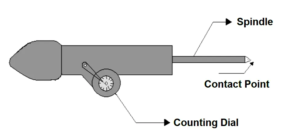
Fig 1: Revolution Tachometer
A revolution counter is manually held for measuring the speed. The worm gear attached to the spindle is rotated by pressing the contact point of the spindle against the rotating shaft whose rotating speed is measured. The worm gear moves a calibrated dial through a spur gear, indicating total revolution of the spindle which is in contact with the shaft.
The stopwatch is started and stopped simultaneously which counts the progress and by this average speed is calculated. Starting and stopping the stopwatch manually was not feasible. So tachoscopes were provided with some of the models in which a counter is combined with a timepiece.
By this method, the timer and stopwatch were pressed simultaneously when the contact was pressed against the rotating shaft and stopped when the pointer was removed. There are some other arrangements also available in an automatic timer in which a ratchet arrangement on a measuring wheel frees the wheel for a definite time and the pointer on the wheel indicates speed directly in rpm on a calibrated dial.
Resonance Tachometer
Resonance tachometer basically works with a vibrating reed-type speed indicator which senses the repeated machine’s vibration frequency due to the reciprocating movement of the pistons, for the measurement of the speed of the engines. It consists of a series of tuned steel reeds of various lengths.
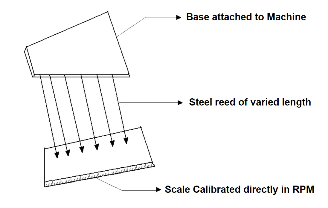
Fig 2: Resonance Tachometer
One part is fixed to the base which is kept in contact with the moving part of the machine and the other part of the read is attached to the part at the bottom of which a calibrated scale is attached that gives reading directly in rpm.
In this when the speed of the machine increases vibration of the machine base also increases as the resonance tachometer is fixed into the base. Because of the resonance tachometer is also vibrating. This vibration changes the speed of the machine. This vibration is calibrated to read the speed of the machine.
To measure the speed of the engine, the reeds that are tuned to resonate with the machine’s vibrating frequency, respond to visibility and indicate speed on a calibrated scale. The range of the resonance tachometer is from 600 to 100,000 rpm. It has a wide range; it is one of the big advantages and this tachometer’s accuracy is the order of 0.5 % or better.
Electrical Tachometer
An electrical tachometer consists of a transducer, recorder, or indicator mainly. This transducer converts the rotational speed into electrical signals and it is coupled with the indicator to indicate the measured value of speed.
The electrical signal may be in the form of analog or digital where the analog indicator is mainly used for analog signals and for digital signals, pulses are digitally counted in terms of revolution in a unit of time.
Types of Electrical Tachometers
- Magnetic Drag Type Tachometer
- Electric Generator Tachometer
- Contact Less Tachometer
- Frequency Tachometer
Magnetic Drag Type Tachometer
In a magnetic drag-type tachometer, the transducer produces an analog signal in the form of a continuous drag due to the eddy current induced in aluminum cup. The induced current is directly proportional to the speed. This is also known as Eddy’s current tachometer. It consists of a Rotor which is coupled to the rotor shaft of the machine whose speed is to be measured. A permanent magnet is attached to the rotor which rotates within an aluminum cup along with the rotor.
A spindle is attached to the aluminum cup, to which the pointer is attached. A hairspring is fixed up to the spindle, which provides the necessary controlling torque. As the magnet rotates within the aluminum cup along with the shaft of the machine where the eddy currents are induced in the cup which results in a torque that makes the cup to turn against the spring.
The deflection of the cup is directly proportional to the induced emf, which in turn is proportional to the speed of the shaft. Deflection is indicated by a pointer which moves on a calibrated dial scale.
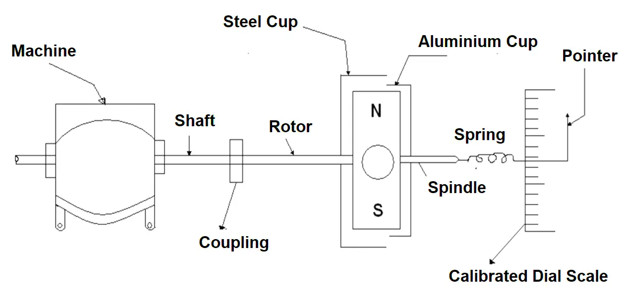
Fig 3: Magnetic Drag Type Tachometer
This type of tachometer is used in automobiles and measures the angular speed of the wheel, then this angular speed is converted into linear speed in kilometers per hour. In aircraft engines, the mechanical coupling of the magnet is replaced by an electric drive consisting of 3 phase synchronous generator driven by a machine shaft under test and connected to 3 phase motor which in turn drives the magnet of the tachometer. In industrial applications, the magnetic drag disk torque is converted to a transmission signal with the help of a pneumatic force-balanced system. Thus, the output pressure of the pneumatic system is directly proportional to the speed of rotation. By this method, we can measure up to 12000 rpm.
Tachometer Generators
It is an electromechanical device that generates a voltage output proportional to shaft speed. It is designed for any unit that can be converted into a function of rotational motion such as rpm, km per hour. There are two types of tachometers generators based upon the functions, they are:
- A.C Tachometer
- D.C Tachometer
A.C Tachometer
A.C Tachometer consists mainly two windings and rotor. In these two windings primary windings are placed mechanically 90 degrees to the secondary. Primary winding is excited by the AC supply, then induced voltage in secondary winding is zero due to relative positions of two winding being placed 90 degrees to each other.
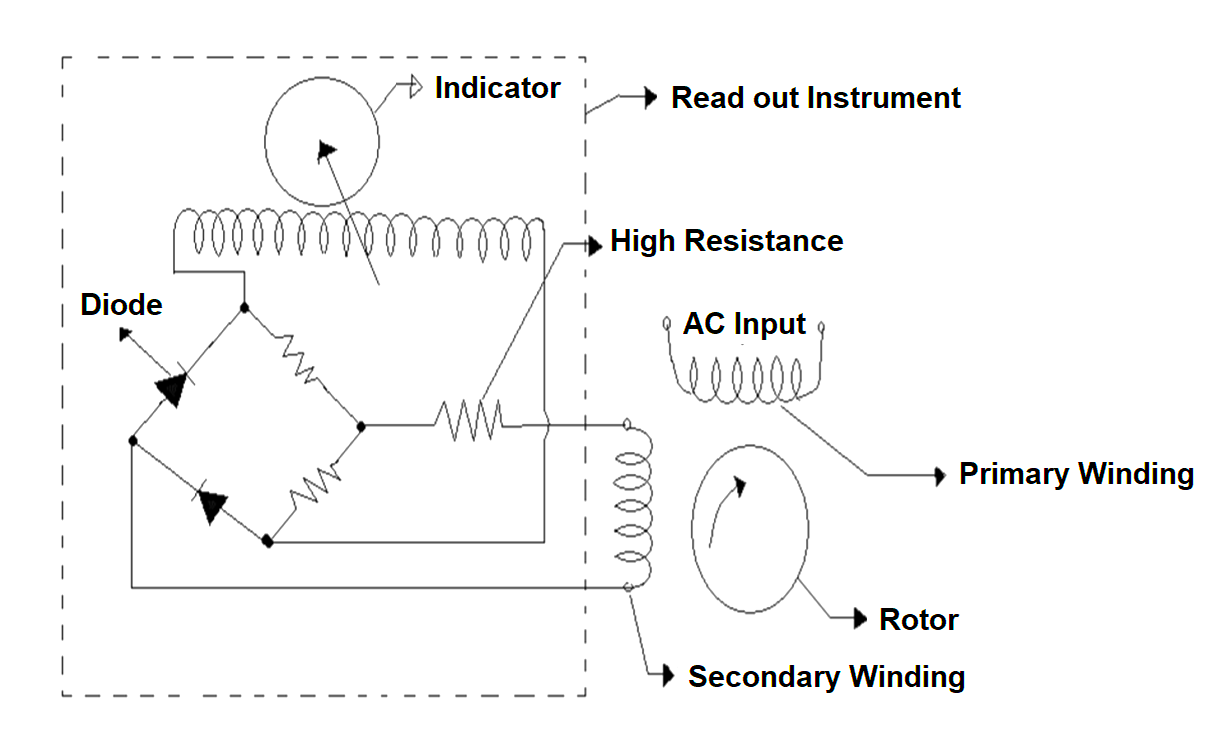
Fig 4 : AC Tachometer
During this case the rotor will not move it will be static position only. When Rotor starts to move, a voltage is induced in the secondary winding whose magnitude is proportional to the rotor speed. Since the output signal is a voltage, a high input resistance is connected with the readout instrument to give near-zero current flow in the secondary winding. Any current flow in the output winding will cause a voltage drop which will be subtracted from the measured voltage and thus give the error in speed measurement. The speed of 500-10000 rpm will be measured in this type of tachometer.
D.C Tachometer
DC Tachometer consists of permanent magnet to provide the magnetic flux and an output winding is placed on the rotor. When the rotor is stationary there is no relative motion between the magnetic field and winding so then the output voltage will be zero in this case.
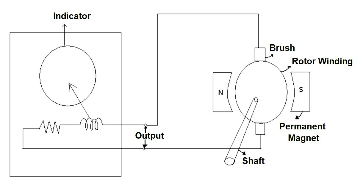
Fig 5: DC Tachometer
As rotor speed increases, the relative motion between the magnetic field and winding also increases so there will be some output voltage will be induced in the winding. This induced voltage will be sinusoidal and their magnitude is proportional to the rotor speed.
Finally, a commutator and brushes are fixed to the rotor to convert the AC voltage in the winding to DC voltage as same as the process of DC Generator. This type of tachometer has the speed of 10 to 5000 rpm.
Contactless Tachometer
The process behind the contactless tachometer is, it produces pulses from a rotating shaft without any mechanical contact. It consists of a cylindrical permanent magnet placed behind a soft iron pole piece around which a coil is wound. The magnet picks up sensor is placed on the shaft gear, made of ferrous material whose speed is to be measured. As the gear rotates the magnetic flux in the soft iron core pole piece becomes high when the tooth of the ferromagnetic gear comes in front of the magnetic pickup, and the flux drops off as the tooth of the gear is passed. Thus the voltage is generated in the coil which is proportional to the rate of change of flux in the pole piece and also proportional to the speed at which the ferromagnetic gear makes the flux build-up.
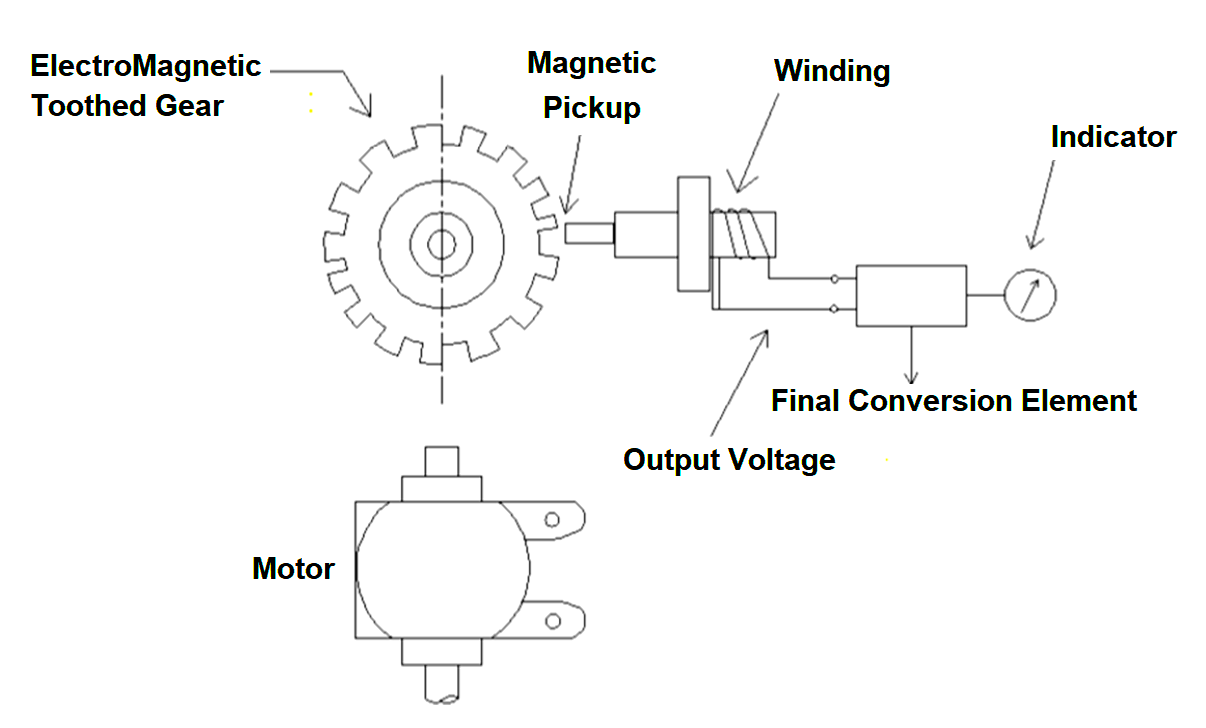
Fig 6: Contact less Tachometer
The output voltage waveform varies depending upon the teeth shape of the gear, thickness and spacing and the output voltage amplitude is proportional to the clearance between the pickup tip and the surface of the gear.
Output frequency is determined by f= (rpm x number of teeth)/60s.
This tachometer gives an accurate indication of speed and it can be used in any type of surface such as vibrating, rotating or moving surface. It can operate under the conditions where oil, water or non-corrosive liquids are present. Available in range from 0 to 72,000 rpm with an accuracy of 0.5 % full scale reading.
Frequency Tachometer
Frequency type tachometer is the frequency meter used as receivers to receive AC signals from a suitable pick up such as multiple generators.
The various type of frequency tachometers are:
- Electronic Counter
- Resonance Frequency Meter
- Vibrating Reed.
Electronic Counter
It consists the revolution per unit of time and is the most accurate and has the widest range.
Resonance Frequency Meter
This type can use a polarized bridge as a null detector and is useful in monitoring speed on an expanded scale, with a narrow range.
Vibrating Reed
In this type of tachometer, the output from an AC generator energies a coil when vibrates reeds at the natural frequency in sympathy with the generator output.