The following are the minimum required documents required for design of pressure gauge datasheet preparation.
Pressure Gauge Datasheet
Lets start with the document requirements !
1. P&ID’s
2. Piping material specifications (PMS)
3. Instrument process datasheets (IPDS)
Additional important documents
4. Client design Basis
5. Finalized Hook-up of Pressure Gauge
6. Model (Navis works) (To check accessibility of Gauge)
Also Important is the “standard” we or the client is going with !!
1.ASME B40.1
2. BS EN 837 –1 (Pressure Gauges Part 1: Bourdon Tube Pressure Gauges – Dimensions, Metrology, Requirements and Testing)
3. IS-3624 (Specification for pressure and vacuum gauges)
4. BSI BS EN 837 –3 (Pressure Gauges Part 3: Diaphragm and Capsule Pressure
Gauges – Dimensions, Metrology, Requirements and Testing)
Note:- As far as I have seen the dominant standard that is preferred by many clients is ASME B40.1
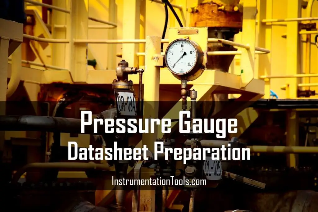
The Pressure Gauge datasheet is divided into 5 Major parts
1. General information :- From P&ID’s
2. Process information :- From IPDS (Instrument process data sheet)
3. Pressure gauge details :- Features ( Element type (C-type and Helical 60 bar-g ), materials, Range and other features required)
4. Accessories :- When to choose what !! (Manifold ,Diaphragm seal , Syphon , snubber , cooling tower , over-pressure protector ,gauge cock ,Remote mounting etc )
5. Tests & Certification :- NDT – Like Radiography , Helium leak test or Dye penetration test to check welds
Lets Explore them in detail !!!
1. General information
This includes things like Line number or Equipment number on which pressure gauge is mounted, schedule of pipe , fluid, P&ID, also Electrical area classification but it is not applicable here as this is mechanical item .
2. Process information
From IPDS (Instrument process data sheet) which is issued from process department as minimum following information must be available in our Datasheet.
3. Operating and Maximum Temperature
The operating temperature and maximum temperature of process conditions.
4. Operating and Maximum Pressure
The operating temperature and maximum pressure of process conditions.
5. Design Pressure and Temperature
Sometimes lower design pressure is also mentioned like FV Full vacuum etc.
6. Process Fluid Type
If applicable special properties like Corrosive , Solid particles etc usually mentioned in notes section of IPDS .
Pressure Gauge Features
The below are the required features of pressure gauge.
Accuracy Requirement
The Accuracy classes are defined in ASME B40.1
We usually go with Grade 2A i.e +/- 0.5 % of span
Remember to check whether required accuracy is available in market . i.e for Low pressure range 0 to 10 psig or lower many vendors provided ± 1% of Full Scale instead of ± 0.5% of Full Scale. Same is the case for very high pressure application .
Material Selection
This a very important consideration to be made during selection
A huge chunk of accidents are reported due to improper material selection
The base document to refer for material selection is Piping material specifications (PMS)
1. Wetted Metallic Part Material Selection
For majority of cases the Pipe is made up of Carbon steel (Refining, Chemical plants etc.) so we prefer SS 316 to be the material for Instrument i.e. Bourdon tube and other wetted parts.
Now the “Tricky” case is for Exotic material , Let us assume the Pipe material is Duplex SS so common sense says we must take the same material for our bourdon tube as it is compatible .
Eg:- Impulse Tubing have typical thickness :- 0.065 inches (Refer standards like :-PIP PCCPR001) so if the service has corrosion rate of 0.125 inches per year so the tube will fail in such cases we must select even more Corrosion resistant metal like Hastelloy etc
If things are unclear consult materials engineer regarding material selection
2. Gasket material selection
( In case of Diaphragm seal gauge )
We cannot blindly accept any material for Gasket .
Chemical compatibility of Gasket material must be checked .
Eg :- FKM vitton is a widely quote gasket material by many vendor to save cost as it is cheaper that PTFE but API RP 551 Page 15 states that a very widely quoted material for gaskets i.e “FKM Vitton” is NOT SUITABLE FOR STEAM.
Elastomers fail in different manners : some swell, some dissolve, and some take a compression set.
Also , Temperature limitation is a limiting factor PTFE is typically used upto 200°C and Graphite/Graphoil upto 450°C
3. Non Wetted part material
These will not come in contact with process but yes this will be in contact with atmosphere .
For Mounting Brackets etc it is important to know the Environment .If it is corrosive to go with SS304 is better if such issues are not there then Galvanized Iron , Steel will also work . This is mostly mentioned in Client Design basis
Eg of Non wetted parts are Case material (usually SS or Phenolic is used ) , movement material (usually SS304 ) Bezel ring etc
Range Selection
The process gives us Min, Normal, Max Pressure values that Pressure gauge has to measure.
Also we Receive Design Pressure and Temperature the Pressure gauge has to withstand.
We have to select a pressure Gauge with Range in such a way the normal operating pressure must be near to 50% of the Range we select ! the Max operating pressure must be at 70% to 80% of the Range we select.
Also if design pressure gets accommodated in this range then its good if not then we much procure a accessory called OPP (Over pressure protector) we will talk in detail about this in accessories section
Example :- IPDS Data
Min. Operating Pressure = 5 Bar-g
Normal Operating Pressure = 10 Bar-g
Max operating Pressure = 15 Bar-g
Design Pressure = 50 Bar-g
Here in the above case Max operating is 15 Barg * 1.3 Times ( This differs could be 1.2 or 1.1 Times) =15* 1.3 =19.5 Bar-g
So select a standard range either from Gauge Standard like ASME B40.1 or approved vendors catalog .
Lets select a range of 0 to 20 Bar-g
But you see the design pressure is difficult to accommodate so we will go with OPP to protect the case if Design conditions occur .
If design pressure would have been 22 Bar-g or so we could have selected a higher range and accommodate it .
Pressure gauge connection to Process
Type :-
Threaded , Flanged Diaphragm seal also threaded diaphragm seal connection is available ! (this will be explained in detail in next article)
Size :-
Threaded then ½ inch , Flanged Diaphragm seal then 2 inch is preferred
Entry :-
Bottom or side entry
Accessibility :-
The gauge must checked in model whether its position is readable to the operator.
In case it is not then either the Dial size could be increase so it is visible from far or Remote mounting has to be suggested .
Generally it is discouraged for remote mounting of pressure gauge to best we can .
Liquid Filled or Dry Gauge or Dampened Gauge :-
Depends on Client Design basis in case of absence of design basis, Glycerin filled must be used where vibration is present . It reduces the fluctuation in pointed of gauge.
Also we must know When “NOT” to go for Glycerin or silicone Filled gauges :- These fluids must be avoided where strong oxidizing agents including, but not limited to, oxygen, chlorine, nitric acid, and hydrogen peroxide are involved.
In the presence of oxidizing agents, potential hazard can result from chemical reaction, ignition, or explosion. Completely fluorinated or chlorinated fluids, or both, may be more suitable for such applications. (Reference ASME B40.1 Page 21)
Other Gauge requirements
There are some features to be mentioned in datasheet, as follows.
Pressure Range
Gauge Pressure ,Absolute pressure , Component Range (Mix of gauge and vacuum )
The Glass on Pressure gauge
Toughened Glass , Shatter proof glass or normal glass (not recommended) and for Higher Pressures it is advisable to go for Solid front design .
Blow out disk
It is at the back
Dial color
Standard is white with Black numerals but client can have his own choice
Dial size
Standard is 4 ½ inch . ASME B40.1 has criteria to select dial of other ranges .
Scale type
Single scale dual scale with different units or Uniform or suppressed scale or
Bezel Type
Bayonet , Snap on , Threaded
I hope it was helpful ! I would glad to know if I have missed points or need correction !!
Thanks for reading !
Author : Asad Shaikh
Profile : Linkedin
Articles You May Like
What is Pressure Gauge Damping
Transmitter Static Pressure Limit
Orifice Flow Meter Flange Rating
How to Solve Cable Tray Hanging
Thermowell Insulation Thickness
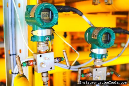
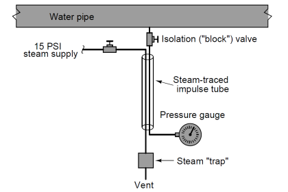






Hi, my name is Jhojan Núñez and I have a question that I appreciate you help me to understand,how can I know the correct position of a pressure gauge in a pipe, depend the type of fluid, e.g: gas, luquid, steam. Thanks
Generally, think you could consider place:
1. high temperature, gas both in process and environment
2. A place have less thickness
3. A place have change in fluid velocity or pressure
4. A place is wetted or I would say it’s changed the structure in side
Asad. this article is more informatic and really very helpful who want to start a career in Instrument design. Thank you for the PG detailed information