Complete set of Questions and Answers on Thermocouple, Resistance thermometers, Thermowell and more Temperature Sensors Interview Questions.
Temperature Sensors Interview Questions

Resistance thermometers
What is RTD class A and class B ?
In the world of RTDs (Resistance Temperature Detectors), platinum has gained enormous popularity. This is due to the physical characteristics that make it superior to other materials for sensing temperature.
To provide interchangeability between manufacturers for the sake of global industry, there are some international standards that have been adopted by most countries:
- IEC 60751 defines the temperature accuracy and the resistance/temperature characteristic curve for several tolerance classes
- “Class B” and “Class A” are the most common tolerance classes.
These are defined by a single nominal resistance/temperature characteristic curve and the following accuracy designations:

There are a number of standards that either copy or are predecessors of IEC 60751.
Among them are IEC 751, DIN 43760, EN 60751, and BS EN 60751.
Another standard, ASTM E1137, uses the same nominal characteristic curve, but defines tolerances differently, and designates them as “Grade B” and “Grade A”. The ASTM standard is not used as widely as the IEC standard.
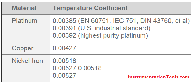
What type of alpha (TCR) curve to use for RTD?
TCR (Temperature coefficient of Resistance) is the normalized average change in resistance of a sensing element over a specific temperature range (typically 0 to 100C).
The value is independent of the base resistance and is a characteristic of the element material itself. The units are measured in ohms/ohm/C.
Example: A probe may read 100 ohms at 0°C, but at 100°C, the .00385 probe will read 138.5 ohms and the .00392 probe will read 139.20 ohms.
A. Resistance curve depends on instrumentation. Refer to your instrumentation manual for acceptable RTD (Resistance Temperature Detector) input types.
B. Common TCRs include:

When we need a Transmitter for RTD Sensor?
There are no firm rules on when to specify transmitters for RTD. Each temperature monitoring system has unique cost and accuracy requirements, and unique design problems to overcome.
In general, transmitters offer three advantages:
- Eliminate lead effects from temperature readings
- Output is more immune to electrical noise
- Condition the RTD (Resistance Temperature Detector) signal
A. RTD leads effects :
Distance between sensors and control points are an obvious reason to specify transmitters.
Factors to consider:
- Transmitters are more accurate than 2-wire RTDs, if this distance is more than a few feet
- Over large distances, even 3-wire RTD’s can be inadequate for the required accuracy
- 4-wire RTD measurement circuits will effectively eliminate lead wire errors, but the space and cost of two extra leads may exceed the cost of a transmitter
- High resistance sensing elements reduce the effects of lead resistance, but do not eliminate them
- RTD measurement circuits are typically low signal (1 mA or less), and are prone to electrical noise – especially in long wire runs.
- At distances over 500 feet, a transmitter may be the only way to carry the accuracy of the RTD to the control electronics
B. Electrical Noise:
Noise from motors, fluorescent lamps, or other sources will degrade resistance or voltage signals, but has little effect on a transmitter’s controlled current.
You may therefore want to use transmitters over relatively short distances in especially noisy areas. The transmitter may even cost less than specially shielded extension wires.
Simply twisting the transmitter wire pair is very effective at reducing noise; shielded cable is usually not necessary.
C. Signal Conditioning:
You may want transmitters for their signal conditioning circuitry alone. RTD resistance/temperature curves are non-linear.
A transmitter changes the RTD resistance to an industry standard 4-20 mA, while simultaneously linearizing the output with temperature. With the transmitter’s linear response, you don’t need complex equations to interpret readings.
When we use shielded lead wires ?
Environments containing high voltages or in the presence of electromagnetic fields (EMF) may require shielded lead wires.
These environments generate what is commonly referred to as “noise” (EMI) within a sensing instrument. Lead wires act as antennas.
Two common techniques may help alleviate the influence of electrical noise:
- Twisting the leads will help offset the induced noise.
- Lead wires may be covered with a “shielding”, commonly silver plated copper braid (SPC Braid). Grounding the shielding at the instrument only provides the best results.
Thermocouples
Difference between grounded and ungrounded thermocouple?
A thermocouple is called “grounded” when the sensing junction is connected (physically and electrically) to the metal case.
There are advantages and disadvantages but generally ungrounded thermocouples are preferable, providing a slower response time is acceptable.

What is a cold (reference) junction for thermocouples?
Cold, or reference junction, is the end of a thermocouple that provides a reference point.
Thermocouples measure the difference in temperature between two junctions. They do NOT measure actual temperature. The sensing junction is where the thermocouple wires are welded (or otherwise connected) together, and located at a point where the temperature is desired.
The other junction is typically located where it is connected to instrumentation (measuring device). This is known as the cold or reference junction.
Thermocouple millivolt tables and mathematical formulas are based on a cold junction temperature of 0°C. To determine actual temperature, the instrumentation must “adjust” for the difference between ambient temperature and 0°C. This adjustment is known as cold junction compensation.
When we need an electrically isolated probe?
To prevent an uncontrolled ground path, electrically isolated probes should be used in insulated bearings, where bearings may be electrically “hot”.
Motors and generators may have insulated bearings to prevent electrostatic discharge and dissipate through a controlled path such as an earth brush.
In this condition, a grounded probe may cause damage to the instrumentation as well as damage to the bearings.
How to specify an assembly (U length, Insertion Length, Probe Length, Etc)
A. Insertion depth is used when an assembly does not utilize a thermowell. Defined as the distance including 50% of the process threads, down to the tip of the probe.
B. Probe length is the complete length of the probe including the length extended inside the connection head. Probe length is calculated by Insertion depth + fitting adder ‘A’.
C. U length is used when an assembly utilizes a thermowell. Defined as the distance from the tip of the thermowell up to the beginning of the process threads.
D. Spring loaded holders offer a little length tolerance flexibility when combining these into an assembly.
What size thermowell is appropriate for my application?
Based on the design of your system you need to know:
- Operating temperature (°C)
- Operating pressure (bar), Specific volume (m3/kg)
- Velocity (m/s)
Once those are established then you’re ready to consult ASME standard PTC 19.3 TW-2010 Thermowell section, which goes through the calculation for the design of the well.
Here are some basic rules you can follow*:
- In general, higher flow velocity requires shorter thermowells.
- Make sure the thermowell material is compatible with the medium in which it is immersed.
- Economical welded thermowells may be used in low flow applications such as some HVAC chiller lines (typically less than 1-3 ft/sec).
- Tapered thermowells are typically better suited for high flow velocities than step (reduced-tip) thermowells.
RTD Questions & Answers
RTD (Resistance Temperature Detector)
An acronym for resistance temperature detector or device. A resistance temperature detector operates on the principle of the change in electrical resistance in wire as a function of temperature.
RTD Element
Sensing portion of the RTD which can be made most commonly of platinum, nickel, or copper. RTD features two styles of elements: wire wound and thin film.
RTD Probe
An assembly composed of an element, a sheath, a lead wire, and a termination or connection. The standard RTD probe is made with a 100 ohm platinum European curve element (alpha = 0.00385).
Platinum RTD
Also known as Pt RTD, Platinum RTD’s are typically the most linear, stable, repeatable, and accurate of all RTD’s. Platinum wire was chosen because it best meets the needs of precision thermoetry.
Thin Film RTD
Thinfilm RTD’s are made up of of a thin layer of a base metal embedded into a ceramic substrate and trimmed to produce the desired resistance value.
RTD’s are made by depositing platinum as a film on a substrate and then encapsulating both. This method allows for the production of small, fast response, accurate sensors. Thin film elements conform to the European curve/DIN 43760 standards and the “0.1% DIN” standard tolerance.
Class A RTD
Highest RTD Element tolerance and accuracy, Class A (IEC-751), Alpha = 0.00385
Class B RTD
Most Common RTD Element tolerance and accuracy, Class B (IEC-751), Alpha = 0.00385
Alpha .00385 Curve
European Curve meets “0.1% DIN” standard tolerance and conforms to the DIN 43760 standard
Sheath
The sheath, a closed end tube, immobilizes the element, protecting it against moisture and the environment to be measured.
The sheath also provides protection and stability to the transition lead wires from the fragile element wires.
RTD’s standard sheaths are 3 mm (1/8″) and 6 mm (1/4″) O. D. 304 stainless steel tubes. Other O.D.’s and materials are available upon request.
Articles You May Like :
-
Thermocouple Questions and Answers
-
RTD Questions and Answers
-
DCS Interview Questions
-
Instrumentation Cables Questions
Thank you sir for the iinformation regarding class A & class B regarding temperature detectors. Request you to plz elaborate it in terms of accuracy.
RTD element are generally 2 types according to standard as per DIN43760.
Class A : It has high accuracy.ice point tolerence is +/- 0.06 ohms.resistance is 0.43 ohms at 600 deg.c
Class B. It is most commnly used element in industry,Ice point tolerance +/- 0.12 Ohms.Resistance is +/- 1.06 ohms at 600 deg.c
Class A accuracy has formula : +/- (0.15 + 0.002 x T)
Class B accuracy has formula : +/- (0.30 + 0.005 x T)
pls give info. for ff
ff transmitter calibration and loop pls info. give
How to measure resistance in 3 wire rtd??? Please explain if u have some example pictures..
Please check Temperature Measurement category posts. Available. Thanks
We use multimeter to check the resistance of the 3 wire RTD during the calibration.
Dear Sir
Is it possible to calibrate two temperature gauge (same rang 0-100°c) in a standard temperature bath at the same time?
1. Is their any standard violation?
2.It may affect the accuracy of the calibration?
3.or it will affect the temperature element ?
I hope you will replay my question…?
By
Nitto
Qa/Qc Eng
Hi,
Yes, you can do that. No Standard Violation. Accuracy & Temperature element have no effect. Click Here for Calibration Baths info. Thanks.
We can calibrate same time more 5 to 10 temperature gauge in the same bath.
No effect on accuracy of the gauge.
Thank you so much for all information.
It is very helpful to us. ..and begins of engineering work..