Thermocouple Questions and Answers

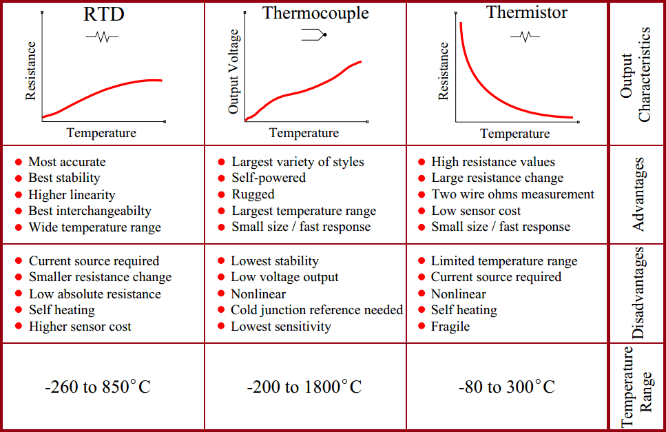
Comparison of Thermocouples, RTD & Thermistor ?
What is a Thermocouple?
A Thermocouple is a sensor used to measure temperature. Thermocouples consist of two wire legs made from different metals. The wires legs are welded together at one end, creating a junction.
This junction is where the temperature is measured. When the junction experiences a change in temperature, a voltage is created. The voltage can then be interpreted using thermocouple reference tables (linked) to calculate the temperature.
There are many types of thermocouples, each with its own unique characteristics in terms of temperature range, durability, vibration resistance, chemical resistance, and application compatibility.
Type J, K, T, & E are “Base Metal” thermocouples, the most common types of thermocouples. Type R, S, and B thermocouples are “Noble Metal” thermocouples, which are used in high temperature applications (see thermocouple temperature ranges.
Thermocouples are used in many industrial, scientific, and OEM applications. They can be found in nearly all industrial markets: Power Generation, Oil/Gas, Pharmaceutical, BioTech, Cement, Paper & Pulp, etc. Thermocouples are also used in everyday appliances like stoves, furnaces, and toasters.
Thermocouples are typically selected because of their low cost, high temperature limits, wide temperature ranges, and durable nature.
What is a cold (reference) junction for thermocouples?
Cold, or reference junction, is the end of a thermocouple that provides a reference point.
Thermocouples measure the difference in temperature between two junctions. They do NOT measure actual temperature. The sensing junction is where the thermocouple wires are welded (or otherwise connected) together, and located at a point where the temperature is desired.
The other junction is typically located where it is connected to instrumentation (measuring device or transmitter). This is known as the cold or reference junction.
Thermocouple millivolt tables and mathematical formulas are based on a cold junction temperature of 0°C. To determine actual temperature, the instrumentation must “adjust” for the difference between ambient temperature and 0°C. This adjustment is known as cold junction compensation.
Also Read : Thermocouples Green Rot Effect
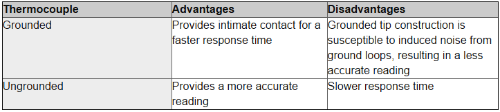
Grounded or ungrounded thermocouple?
A thermocouple is called “grounded” when the sensing junction is connected (physically and electrically) to the metal case.
There are advantages and disadvantages but generally ungrounded thermocouples are preferable, providing a slower response time is acceptable.
What is the difference between a Thermocouple and RTD?
Temperature Range
First, consider the difference in temperature ranges. Noble Metal Thermocouples can reach 3,100 F, while standard RTDs have a limit of 600 F and extended range RTDs have a limit of 1,100 F.
Cost
A plain stem thermocouple is 2 to 3 times less expensive than a plain stem RTD.
A thermocouple head assembly is roughly 50% less expensive than an equivalent RTD head assembly.
Accuracy, Linearity, & Stability
As a general rule, RTDs are more accurate than thermocouples. This is especially true at lower temperature ranges.
RTDs are also more stable and have better linearity than thermocouples. If accuracy, linearity, and stability are your primary concerns and your application is within an RTD’s temperature limits, go with the RTD.
Durability
In the sensors industry, RTDs are widely regarded as a less durable sensor when compared to thermocouples.
Response Time
RTDs cannot be grounded. For this reason, they have a slower response time than grounded thermocouples.
Also, thermocouples can be placed inside a smaller diameter sheath than RTDs.
A smaller sheath diameter will increase response time. For example, a grounded thermocouple inside a 1/16” dia.
sheath will have a faster response time than a RTD inside a ¼” dia. sheath
What are the thermocouple junction types?
Grounded Thermocouples :
This is the most common junction style. A thermocouple is grounded when both thermocouple wires and the sheath are all welded together to form one junction at the probe tip.
Grounded thermocouples have a very good response time because the thermocouple is making direct contact with the sheath, allowing heat to transfer easily.
A drawback of the grounded thermocouple is that the thermocouple is more susceptible to electrical interference. This is because the sheath often comes into contact with the surrounding area, providing a path for interference.
Ungrounded Thermocouples :
A thermocouple is ungrounded when the thermocouple wires are welded together but they are insulated from the sheath.
The wires are often separated by mineral insulation.
Exposed Thermocouples (or “bare wire thermocouples”) :
A thermocouple is exposed when the thermocouple wires are welded together and directly inserted into the process.
The response time is very quick, but exposed thermocouple wires are more prone to corrosion and degradation. Unless your application requires exposed junctions, this style is not recommended.
Ungrounded Uncommon :
An ungrounded uncommon thermocouple consists of a dual thermocouple that is insulated from the sheath and each of the elements are insulated from one other.
What is M.I. Cable?
M.I. (Mineral Insulated) cable is used to insulate thermocouple wires from one another and from the metal sheath that surrounds them.
MI Cable has two (or four when duplex) thermocouple wires running down the middle of the tube.
The tube is then filled with magnesium oxide powder and compacted to ensure the wires are properly insulated and separated.
MI cable helps to protect the thermocouple wire from corrosion and electrical interference.
How are the Thermocouple Sheaths different?
- 316SS (stainless steel): This is the most common sheath material. It is relatively corrosion resistant and is cost effective.
- 304SS: This sheath is not as corrosion resistant as 316SS. The cost difference between 316SS and 304SS is nominal.
- Inconel (registered trademark) 600: This material is recommended for highly corrosive environments.
Also Read : Thermocouple Calibration
What do thermocouple wire colors indicate?
A thermocouple can be identified by the color of its wire insulation.
For example, in the United States a type J thermocouple grade wire has one red wire and one white wire, typically with a brown over jacket.
A type J extension grade wire also has one red wire and one white wire, but it has a black over jacket.
As a general rule the red wire of a thermocouple or extension wire is negative and the positive wire is color coded according to the type of thermocouple.
Different countries use different color codes.
What is the difference between thermocouple wire cable and extension grade wire?
Thermocouple grade wire is used to manufacture thermocouple probes.
Thermocouple grade wire is normally used for the junction and inside the stem sheath. This is because the thermocouple grade wire has a better accuracy specification than extension grade wire.
Extension grade wire is a less expensive, lower grade wire. It is used to extend the signal from the thermocouple probe to the control system or digital display.
Extension grade wire is more economical due to a lesser grade metal being used.
Extension grade wire should not be used in the process itself and should not see the temperature extremes & temperature cycling as standard grade wire.
What is Seebeck effect?
When two wires of different metals or metal alloys (thermo wires) are joined together in one end (hot junction), a thermocouple is formed.
If there is a temperature difference between the hot junction and the open ends, a thermal electromotive force (a thermal voltage) is created in the thermocouple. This is also called the Seebeck effect.
What is CJC?
A thermocouple measurement always needs information from joined wire end (hot junction) and open wire end (cold junction). The cold junction is also called reference point.
Variations of reference point temperature are compensated with CJC measuring (Cold Junction Compensation).
Temperature transmitters CJC measuring can be an internal function or a measuring resistor integrated in connectors.
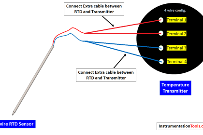
If the reference point is far away from the transmitter, a separate temperature measuring of that point has to be implemented and wired to transmitter as compensation signal.
What is Compensating cable and Extension cable?
Compensating cable is a thermocouple measuring circuit cable, which is identified by the letter C (e.g. for type K cable KC).
Wires of the compensating cable have the same electrical features, but not the same materials, as the thermo wires of the TC sensor.
Compensating cable is a more cost effective solution than extension cable, but the maximum ambient temperature allowed is lower, approximately 100…200 °C depending on the insulation material.
Extension cable is a thermocouple cable which is identified by the letter X (e.g. for type K cable KX). Wires of the extension cable are of exactly the same materials as the thermo wires of the TC sensor.
These cables can achieve even the same ambient temperatures as the thermocouple can.
What is trace heating / sensor?
Trace heating is a term usually used for keeping pipelines and attached devices unfrozen.
The important function of trace heating is maintaining stable temperature and flow rate of the materials flowing through the pipeline.
The most common implementation of trace heating is electrical, which offers good adjustability.
However, for accurate process control and adjustment also precise temperature data is needed.
For these applications we have designed our high quality trace heating sensors, which already have been available for years, also for Ex applications.
What size thermowell is appropriate for my application?
Based on the design of your system you need to know:
- Operating temperature (°C)
- Operating pressure (bar), Specific volume (m3/kg)
- Velocity (m/s)
Once those are established then you’re ready to consult ASME standard PTC 19.3 TW-2010 Thermowell section, which goes through the calculation for the design of the well.
Here are some basic rules you can follow*:
- In general, higher flow velocity requires shorter thermowells.
- Make sure the thermowell material is compatible with the medium in which it is immersed.
- Economical welded thermowells may be used in low flow applications such as some HVAC chiller lines (typically less than 1-3 ft/sec).
- Tapered thermowells are typically better suited for high flow velocities than step (reduced-tip) thermowells.
What is Pyrometer and explain its working ?
A Pyrometer is a non-contacting device that intercepts and measures thermal radiations.
Without making any contact with the radiating body and the process is known as pyrometry. This device is useful for determining the temperature of an object’s surface.
Pyrometer strictly works on the principle of black body radiation. Here emissivity of the target plays an important role, as it governs how bright the target appears to the pyrometer.
Due to its high accuracy, speed, economy and specific advantages, it is widely being used as a standard procedure in many industrial applications.
Working:
- An optical system gathers the visible and infrared energy from an object and focuses it to the detector.
- The detector receives the photon energy from the optical system and converts it to an electric signal to drive a temperature display or control unit.
Thermocouples Measuring Junction
An exposed (measuring) junction is recommended for the measurement of flowing or static non-corrosive gas temperature when the greatest sensitivity and quickest response is required.
An insulated junction is more suitable for corrosive media although the thermal response is slower.
In some applications where more than one thermocouple connects to the associated instrumentation, insulation may be essential to avoid spurious signals occurring in the measuring circuits. If not specified, this is the standard.
An earthed (grounded) junction is also suitable for corrosive media and for high pressure applications.
It provides faster response than the insulated junction and protection not offered by the exposed junction.
Also Read : Thermocouples Connector & Tip styles
Thermocouple Standards
- ASTM E 235: Standard Specification for Thermocouples, Sheathed, Type K and Type N for Nuclear or for other High-Reliability Applications.
- ASTM E 839: Standard Test Methods for Sheathed Thermocouples and Sheathed Thermocouple Materials.
- ASTM E 220: Test Methods for Calibration of Thermocouples by Comparison Techniques
- ASTM E 230: Specification and Temperature-EMF Tables for Standardized Thermocouples.
- ASTM E 585: Standard specification for compacted MI, MS, base metal thermocouple cables.
- ASTM E 608: Standard specification for compacted MI, MS, base metal thermocouples.
- ASTM E 696: Standard specifications for tungsten – rhenium alloy thermocouple wire.
- ASTM E 1652: Standard specification for Magnesium oxide & Alumina oxide powder & crushable insulators used in metal sheathed PRT’s, base metal thermocouples & noble metal thermocouple.
- IS 12579: Specification for Base Metal Mineral Insulated Thermocouple Cables and Thermocouples.
- GB/T 1598- 2010: Chinese standard for platinum thermocouples.
- IEC 584: International standard for thermocouples.
Applications of Thermowells
Thermowells provide protection for temperature probes against unfavorable operating conditions such as corrosive media, physical impact (e.g. clinker in furnaces) and high pressure gas or liquid.
Their use also permits quick and easy probe interchanging without the need to “open-up” the process.
The main application areas are:
- Protection tube are used in thermocouples
- Insures integrity in high pressure applications
- Smaller wells are used in low pressure applications
- Straight wells are used in corrosive and erosive environment
- For applications where a quick response to changes in temperature is required, fabricated pockets may be fitted with a reduced tip.
One-piece Thermowells are suited to the highest process loads, depending on their design. Thus in the petrochemical industry, one-piece thermocouples are now used almost exclusively.
Types of Thermocouple Constructions
There are two types of thermocouple construction used most commonly.
These are Mineral Insulated (M.I.) Thermocouples & Non M.I. Thermocouples.
Mineral Insulated Thermocouples :
Magnesium Oxide insulated thermocouples, are used in many process and laboratory applications.
They are rugged in nature and bendable, and their fairly high temperature ratings make MgO thermocouples a popular choice for a multitude of temperature measuring applications.
MgO sensors are constructed by placing an element or elements into a sheath of a suitable material and size, insulating the elements from themselves and the sheath with loose filled or crushable Magnesium Oxide powder or insulators, and then swaging or drawing the filled sheath down to its final reduced size.
The swaging process produces an element with highly compacted MgO insulation and provides high dielectric strength insulation between the elements themselves and their sheath.
Mineral insulated Thermocouples consist of thermocouple wire embedded in a densely packed refractory oxide powder insulate all enclosed in a seamless, drawn metal sheath (usually stainless steel).
At one end cores and sheath are welded from a “hot” junction. At the other end, the thermocouple is connected to a “transition” of extension wires, connecting head or connector.
Non M.I. Thermocouples
In Non-M.I. thermocouples, thermocouple wires are either insulated with ceramic beads or after insulation of ceramic, covered by a metal sheath (usually stainless steel) and some form of termination (extension lead, connecting head or connector for example) is provided.
In this type of construction thermocouple wires are protected from the measuring environment when a sheath protection is provided.
The sheath material is dependent on the measuring environment usually stainless steel is used. According to the corrosive environment sheath selection is changed.
This construction does not provide flexibility & not found in small sizes. Not too good mechanical strength.
In Non M.I. construction sheath may be of ceramic or metal as per suitability.
Exposed, Grounded and Ungrounded all types of junctions are formed in both the M.I, & Non M.I. construction.
Characteristics of thermocouple
Tolerances on Temperature Reading
Tolerance denotes the maximum allowable value obtained by subtracting the temperature reading or the temperature at the hot junction from the standard temperature converted from the applicable temperature EMF table.
Maximum Operating Temperature
Operating temperature limit means the upper temperature where thermocouple can be used continuously in air.
Maximum limit means the upper temperature where thermocouple can be used temporarily for short period of time owing to unavoidable circumstances.
Principal factors that affect the life of a thermocouple are:
- Temperature: Thermocouple life decreases by about 50% when an increase of 50 °C occurs.
- Diameter: By doubling the diameter of the wire, the life increases by 2-3 times.
- Thermic cycling: When thermocouples are exposed to thermic cycling from room temperature to above 500°C, their life decreases by about 50% compared to a thermocouple used continuously at the same temperature.
- Protection: When thermocouples are covered by a protective sheath and placed into ceramic insulators, their life is considerably extended.
Thermocouple Response Times
The response time for a thermocouple is usually defined as the time taken for the thermal voltage (output) to reach 63% of maximum for the step change temperature.
It is dependent on several parameters including the thermocouple dimension, construction, tip configuration and the nature of the medium in which the sensor is located.
Immersion Length
Thermocouple assemblies are” tip” sensing devices which lend them to both surface and immersion applications depending on their construction.
However immersion type must be used carefully to avoid error due to stema conduction from the process which can result in a high or low reading respectively.
A general rule is to immerse into the medium to a minimum of 4 times the outside diameter of them sheath; no quantitative data applies but care must be exercised in order to obtain meaningful results.
Surface Temperature Measurement
Although thermocouple assemblies are primarily tip sensing devices, the use of protection tubes renders surface sensing impractical.
Physically, the probe does not lend itself to surface presentation and steam conduction would cause reading errors.
If thermocouple is to be used reliably for surface sensing, it must be either exposed, welded junction from with very small thermal mass or be housed in a construction, which permits true surface contact when attaching to the surface.
Thermowell Tip profiles
The following are the different thermowell tip profiles :
Tapered
The outside diameter decreases gradually along the immersion length. Used for high velocity applications.
Flat Tip
It one end has flat surface. Used in low pressure applications or where flow characteristics around the thermowell are not important.
Domed Tip
- Such thermowell has semi-spherical tip at one end of thermowell.
- Used in higher pressure applications or where flow characteristics around the thermowell are important.
- This ensures a high degree of mechanical strength without losing the sensitivity or accuracy of the indicator
Spherical Tip
- For spherical tip, special drill is used with a tip angle of 118ºC for production of thermowell.
- To achieve a possible uniform wall thickness, the tip is ball shaped or spherical in shape.
- Used in higher pressure applications or where flow characteristics around the thermowell are important.
- This ensures a high degree of mechanical strength without losing the sensitivity or accuracy of the indicator.
Basic construction of Thermowells
- Q Dimension: The thickest part of the shank of the well on the hot side of the process connection or flange. It is dependent on the bore size and the process connection size.
- Bore Size The inside diameter of thermowell. In other words, the diameter of the internal cylindrical cavity of a thermowell or protection tube Standard bore sizes are 6.5 mm, 8.5 mm.
- Immersion (“U”) Length: The length of a thermowell or protection tube below the mounting threads, flange, bushing, etc. extending into the process area. The “U” length is measured from the bottom of the process connection to the tip of the thermowell.
- Lagging Extension (“T”) Length: The length of a thermowell, in addition to the standard head lengths, required to make the head of the thermowell accessible and this enable the probe to extend through insulation or walls.
- Internal Mounting Thread: The thread within the thermowell for attaching a temperature device of the union and nipple extension for a thermowell assembly.
Tests on Thermowells
- Material Test
- Dimensional Test
- Hydrostatic Pressure Test
- Dye Penetrant Inspection
- Radiography
How to Choose a Thermocouple ?
Because a thermocouple measures in wide temperature ranges and can be relatively rugged, thermocouples are very often used in industry.
The following criteria are used in selecting a thermocouple:
- Temperature range
- Chemical resistance of the thermocouple or sheath material
- Abrasion and vibration resistance
- Installation requirements (may need to be compatible with existing equipment; existing holes may determine probe diameter)
What is the response time of a thermocouple?
A time constant has been defined as the time required by a sensor to reach 63.2% of a step change in temperature under a specified set of conditions.
Five time constants are required for the sensor to approach 100% of the step change value. An exposed junction thermocouple offers the fastest response.
Also, the smaller the probe sheath diameter, the faster the response, but the maximum temperature may be lower.
Be aware, however, that sometimes the probe sheath cannot withstand the full temperature range of the thermocouple type.
Download : Thermocouple Calculator
How do we know which junction type to choose?
- Sheathed thermocouple probes are available with one of three junction types: grounded, ungrounded or exposed.
- At the tip of a grounded junction probe, the thermocouple wires are physically attached to the inside of the probe wall.
- This results in good heat transfer from the outside, through the probe wall to the thermocouple junction.
- In an ungrounded probe, the thermocouple junction is detached from the probe wall.
- Response time is slower than the grounded style, but the ungrounded offers electrical isolation.
How to choose between thermocouples, resistance temperature detectors (RTD’s), thermistors and infrared devices?
You have to consider the characteristics and costs of the various sensors as well as the available instrumentation.
In addition, Thermocouples generally can measure temperatures over wide temperature ranges, inexpensively, and are very rugged, but they are not as accurate or stable as RTD’s and thermistors.
RTD’s are stable and have a fairly wide temperature range, but are not as rugged and inexpensive as thermocouples.
Since they require the use of electric current to make measurements, RTD’s are subject to inaccuracies from self-heating.
Thermistors tend to be more accurate than RTD’s or thermocouples, but they have a much more limited temperature range. They are also subject to selfheating.
Infrared Sensors can be used to measure temperatures higher than any of the other devices and do so without direct contact with the surfaces being measured.
However, they are generally not as accurate and are sensitive to surface radiation efficiency (or more precisely, surface emissivity).
Using fiber optic cables, they can measure surfaces that are not within a direct line of sight.
What are the Thermocouple types ?
Thermocouples are available in different combinations of metals or calibrations. The most common are the “Base Metal” thermocouples known as Types J, K, T, E and N.
There are also high temperature calibrations – als known as Noble Metal thermocouples – Types R, S, C and GB.
K Type Thermocouples are known as general purpose thermocouple due to its low cost and temperature range.
This high temperature wire/thermocouple is produced using a wide range of materials, and is available with PVC, FEP, TFE, PFA, Fiberglass, and Ceramaflex insulation.
However, if you see it referenced by “type” on a spec sheet, the description is referring to the kind of metal alloy used for the wire’s conductor:
- Type E = Chromel/Constantan
- Type J = Iron/Constantan
- Type K = Chromel/Alumel
- Type N = Nicrosil/Nisil
- Type T = Copper/Constantan
When an “X” follows the letter indicating which alloy was used in the cable, the cable is extension grade.
In these cases, the types of cable are listed as Type EX, Type JX, Type KX, Type NX, or Type TX.
| Common Thermocouple Temperature Ranges | |||
| Calibration | Temperature Range |
Standard Limits of Error |
Special Limits of Error |
|---|---|---|---|
| J | 0° to 750°C (32° to 1382°F) |
Greater of 2.2°C or 0.75% |
Greater of 1.1°C or 0.4% |
| K | -200° to 1250°C (-328° to 2282°F) |
Greater of 2.2°C or 0.75% |
Greater of 1.1°C or 0.4% |
| E | -200° to 900°C (-328° to 1652°F) |
Greater of 1.7°C or 0.5% |
Greater of 1.0°C or 0.4% |
| T | -250° to 350°C (-328° to 662°F) |
Greater of 1.0°C or 0.75% |
Greater of 0.5°C or 0.4% |
What is the difference between thermocouple grade wire and extension grade wire?
This wire that is used to make the sensing point of the instrument, where extension grade wire is only used to extend a thermocouple signal from a probe back to the instrument reading the signal.
Thermocouple Material Selection ?
The various sheath materials are dependent upon the application.
The following list will help you make the best selection:
- 304 SS
Maximum temperature of 1650°F (900°C) and is the most widely used low temperature sheath material. It offers good corrosion resistance but is subject to carbide precipitation in the 900°F to 1600°F (480 to 870°C) range. - 310 SS
Maximum temperature of 2100°F (1150°C) and offers good mechanical and corrosion resistance similar to 304 SS. Very good heat resistance. Not as ductile as 304 SS. - 316 S
Maximum temperature of 1650°F (900°C) and has the best corrosion resistance of the austenitic stainless steels. Subject to carbide precipitation in the 900°F to 1600°F (480 to 870°C) - Inconel®
Maximum temperature 2150°F (1175°C) and is the most widely used thermocouple sheath material. Good high temperature strength, corrosion resistance and is resistant to chloride-ion stress corrosion, cracking and oxidation. Do not use in sulfur bearing environments. - Hastelloy X
Maximum temperature 2200°F (1205°C) widely used in aerospace applications. Resistant to oxidizing, reducing and neutral atmospheric conditions. Excellent high temperature strength.


Very useful information’s included about Thermocouple..
Very useful information about thermo couples.
Thanks for information of thermocouple
thanks alot
Very helpful article to practicing instrumentation engineers.
this site is very much useful for technical information
Please update in Hindi