Inst ToolsInst ToolsInst Tools
  • Courses
  • Automation
    • PLC
    • Control System
    • Safety System
    • Communication
    • Fire & Gas System
  • Instrumentation
    • Design
    • Pressure
    • Temperature
    • Flow
    • Level
    • Vibration
    • Analyzer
    • Control Valve
    • Switch
    • Calibration
    • Erection & Commissioning
  • Interview
    • Instrumentation
    • Electrical
    • Electronics
    • Practical
  • Q&A
    • Instrumentation
    • Control System
    • Electrical
    • Electronics
    • Analog Electronics
    • Digital Electronics
    • Power Electronics
    • Microprocessor
  • Request
Search
  • Books
  • Software
  • Projects
  • Process
  • Tools
  • Basics
  • Formula
  • Power Plant
  • Root Cause Analysis
  • Electrical Basics
  • Animation
  • Standards
  • 4-20 mA Course
  • Siemens PLC Course
Reading: Formula of 2 Wire RTD, 3 Wire RTD & 4 Wire RTD
Share
Notification Show More
Font ResizerAa
Inst ToolsInst Tools
Font ResizerAa
  • Courses
  • Design
  • PLC
  • Interview
  • Control System
Search
  • Courses
  • Automation
    • PLC
    • Control System
    • Safety System
    • Communication
    • Fire & Gas System
  • Instrumentation
    • Design
    • Pressure
    • Temperature
    • Flow
    • Level
    • Vibration
    • Analyzer
    • Control Valve
    • Switch
    • Calibration
    • Erection & Commissioning
  • Interview
    • Instrumentation
    • Electrical
    • Electronics
    • Practical
  • Q&A
    • Instrumentation
    • Control System
    • Electrical
    • Electronics
    • Analog Electronics
    • Digital Electronics
    • Power Electronics
    • Microprocessor
  • Request
Follow US
All rights reserved. Reproduction in whole or in part without written permission is prohibited.
Inst Tools > Blog > Temperature Measurement > Formula of 2 Wire RTD, 3 Wire RTD & 4 Wire RTD

Formula of 2 Wire RTD, 3 Wire RTD & 4 Wire RTD

Last updated: September 4, 2019 8:57 pm
Editorial Staff
Temperature Measurement
No Comments
Share
2 Min Read
SHARE

2 Wire RTD :

Two Wire RTD

Contents
2 Wire RTD :3 Wire RTD :4 Wire RTD :

where

  • Rpt is Resistance of RTD
  • R2 is Resistance of first lead wire (Extension cable used to connect RTD)
  • R3 is Resistance of second lead wire (Extension cable used to connect RTD)
  • L2 & L3 are extension cable leads

The wire resistances R2 and R3 are inevitably included in the measured value. Wire resistance can be cancelled by calibration, but just at one specific temperature of the wire (often room temperature).

Also Read :  Difference Between 2 wire RTD, 3 wire RTD, & 4 wire RTD

3 Wire RTD :

Three Wire RTD

where

  • Rpt is Resistance of RTD
  • R1 is Resistance of first lead wire (Extension cable used to connect RTD)
  • R2 is Resistance of second lead wire (Extension cable used to connect RTD)
  • R3 is Resistance of third lead wire (Extension cable used to connect RTD)
  • L1, L2 & L3 are extension cable leads
  • Ω1 is the total resistance between lead wires L2 & L3
  • Ω2 is the total resistance between lead wires L1 & L2

If and only if the wire resistances R1 and R3 are equal you measure the true Pt100 resistance. As the wire L2 also is coloured red (and hard to follow) you have to keep all the wire resistances R1, R2 and R3 equal.

Also Read : Difference Between RTD, Thermocouple & Thermistor
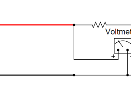
4 Wire RTD :

Four Wire RTD

Full Article : How a 4 wire RTD Works ?

The current source will maintain the excitation current constantly (0.1 – 1 mA). Following the Law of Ohm, R = U / I, the resistance can be calculated. The digital volt meter, DVM, has an input impedance of at least 10 Mohms.

Thus just an extremely small current will pass through the DVM which means that the voltage drops over the wire resistances R2 and R3 will be practically none.

Also Read : RTD Interview Questions & Answers

Source : pentronic.se

Don't Miss Our Updates
Be the first to get exclusive content straight to your email.
We promise not to spam you. You can unsubscribe at any time.
Invalid email address
You've successfully subscribed !

Continue Reading

Pneumatic Temperature Transmitter with Sensor Principle
How to Select Right Thermocouple & Thermowell ?
Thermocouples Burnout detection
What is Temperature ?
Resistance Temperature Detectors (RTD) Construction
Optical Pyrometer Working Principle
Share This Article
Facebook Whatsapp Whatsapp LinkedIn Copy Link
Share
Leave a Comment

Leave a Reply Cancel reply

Your email address will not be published. Required fields are marked *

Stay Connected

128.3kFollowersLike
69.1kFollowersFollow
210kSubscribersSubscribe
38kFollowersFollow

Categories

Explore More

How to calculate Thermocouple Temperature by measuring the output millivoltage
Effect of Lead Wire Resistance on RTD
Questions on Thermocouple and Pyrometer
Testing a Thermocouple With a Multimeter
Temperature Calibration Bath Principle
Thermocouple Details
Thermocouple Working Principle
Basics of Thermocouples and RTD

Keep Learning

RTD

Why 4 wire RTD Measurement Accuracy is better than 2 and 3 wire RTD?

RTD Calculator : Calculate Temperature from Resistance

RTD Calculator : Calculate Temperature from Resistance

non-contact pyrometer principle

Non-contact Temperature Sensors

Thermowell Design Guidelines

Disadvantages of Resistance Temperature Detectors (RTD)

Disadvantages of Resistance Temperature Detectors

What is a Thermostat

Thermostat – Types, Working Principle, Advantages, Applications

thermocouple head

Thermocouples Connector and Tip styles

RTD Standards list

RTD Standards

Learn More

Purpose of Flow Ratio Controller

Identify the Purpose of Flow Ratio Controller

Industrial Instruments Questions and Answers

Industrial Instruments Questions and Answers

Power Electronics Objective Questions

Power Electronics Applications Objective Questions

Effects of Long Distance Cables on VFD

Effects of Long Distance Cables between VFD and Motor

Heat Exchanger Root Cause Analysis

Heat Exchanger Root Cause Analysis (RCA)

PLC Fault Diagnosis - PLC Training Documents

PLC Fault Diagnosis – PLC Training Documents

Electric Stress Control in Cables, Joints and Terminations

Electric Stress Control in Cables, Joints, and Terminations

Compressor and Compressor valves Maintenance

Compressor & Compressor Valves Maintenance

Menu

  • About
  • Privacy Policy
  • Copyright

Quick Links

  • Learn PLC
  • Helping Hand
  • Part Time Job

YouTube Subscribe

Follow US
All rights reserved. Reproduction in whole or in part without written permission is prohibited.
Welcome Back!

Sign in to your account

Username or Email Address
Password

Lost your password?