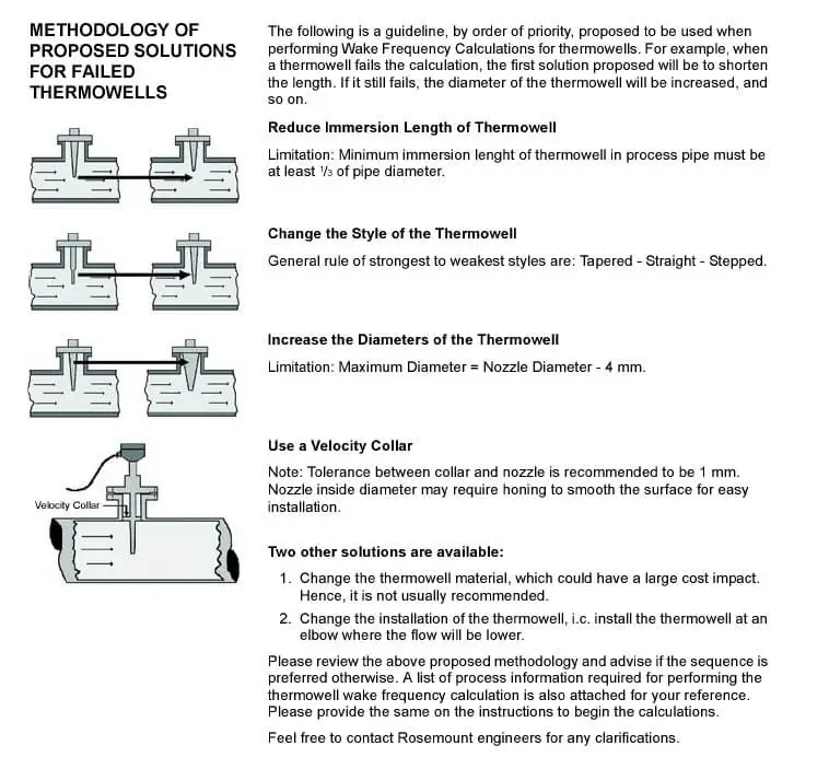
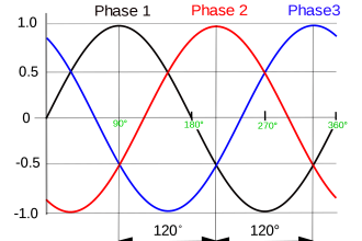
When fluid flows past a thermowell inserted into a pipe or duct, vorticies form at both sides of the well. 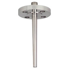 These vorticies detach, first from one side, and then from the other. This phenomenon is known as the Von Karmann effect. The frequency of shedding of these vortices is a function of the diameter of the thermowell, the fluid velocity and, to a lesser extent, the Reynolds number.The vortex shedding subjects the thermowell to a periodic transverse force. As the vortex shedding frequency approaches the natural frequency of the thermowell, the thermowell will oscillate, and is liable to snap off. (The natural frequency of the thermowell is a function of its shape and material of manufacture.)
The Von Karmann effect must be taken into account when designing thermowells of sufficient strength to withstand service conditions, and generally thermowells are chosen such that the shedding frequency is always less than or equal to 80% of the natural frequency.
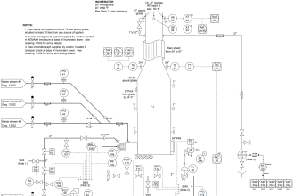
Thermowell points to be taken care-
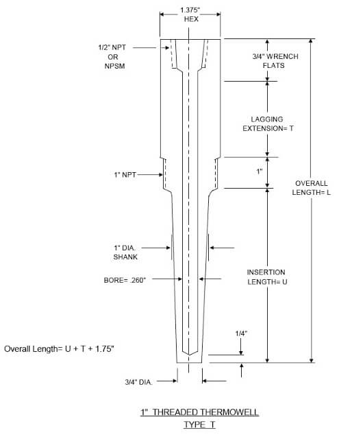
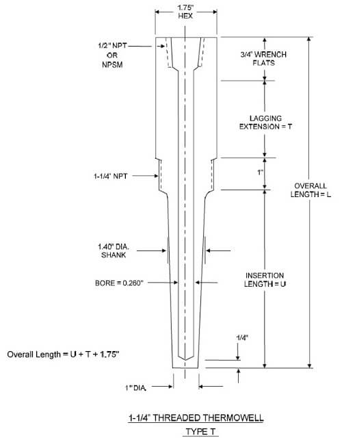
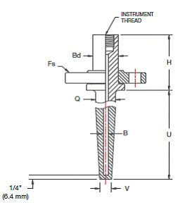
- Bore, “d” shall be 0.26 inch maximum to pass plug gauge of 0.254 inch OD.
- Bore /OD eccentricity shall be +/- 10 percent of minimum wall thickness.
- Bore depth shall be +/- 1/32 inch for depths to 30 inches.
- Overall length, “L” shall be +/- 1/32 inch for lengths to 30 inches.
- Insertion Length, “U” shall be +/- 1/16 inch for lengths to 12 inches and +/- 1/8 inch for lengths over 12 inches.
- Head diameter shall be +/- 0.01 inch
- Shank diameter shall be +/- 0.01 inch
- Tip diameter shall be +/- 1/32 inch
- Tip thickness +/- 1/32 inch
- Thermowells shall have the tag number and material on the well head. For test thermowells, provide 1/2-inch NPT brass plug with brass chain attached to head of well by non-welding technique. Bore drilling may be performed either by twist drill or gun drill.
Thermowells purchased for installation on piping and vessels are categorized into four types:
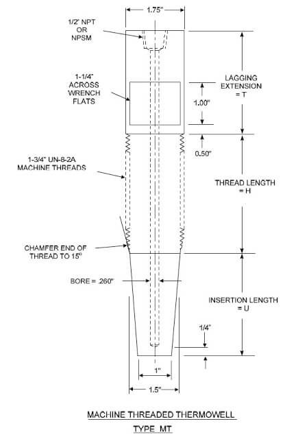
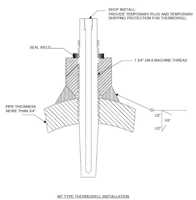
- Machine Thread (“MT” Type) recommended for wall thicknesses more than 3/4 inch;
- 1-inch NPT Threaded (“T” Type) used for line sizes 6 inches and smaller, with wall thicknesses less than or equal to 3/4-inch;
- 1-1/4 inch NPT Threaded (“T” Type) used for line sizes 8 inches and larger, with wall thicknesses less than or equal to 3/4-inch; and
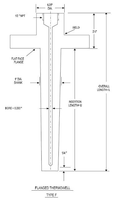
- 3-inch 150# Flanged (“F” Type) used for lined piping, atmospheric tanks and vessels.
Van Stone Thermowells
It is advisable to use full penetration welds for flanged thermowells to achieve the highest fatigue strength rating. Forged thermowells accomplish the same goal without welds, but at a much higher cost. Van Stone style thermowells accomplish this without the cost.
Van Stone termowells are machined from solid bar and are connected using a separate and reusable backing flange. Van Stone termowells mounted between mating flanges for process insertion.
This design offers two advantages:
- Any weld stress is eliminated.
- The slip on flange not being exposed to the process conditions can be of a less expensive material.
Applications:
- Chemical, process, apparatus and plantengineering; petrochemical; on/offshore
- High chemical loads
- High process loads
Also Read: Thermowell Insertion & ImmersionLength


Please suggest on Welded thermowell with Flange .How much tiled accept with flange referance according to length wise. If possible ,please share all details.
Great
Is anyone aware of a specification covering PT100 contact area within a Thermowell, or design recommendations.