Proper connections for all three types of RTD sensor (2-wire, 3-wire, and 4-wire) to a user configurable transmitter are shown in the following illustrations:
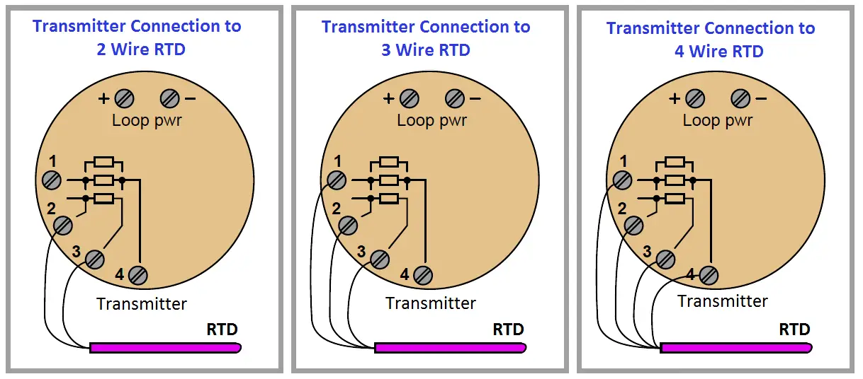
It is critically important to note that the common connections shown by the symbols for 3- and 4-wire RTD sensors represent junction points at the sensor ; not terminals jumpered by the technician at the time of installation, and not internal jumpers inside the transmitter. The whole purpose of having 3-wire and 4-wire RTD circuits is to eliminate errors due to voltage drop along the current-carrying wires, and this can only be realized if the “sensing” wire(s) extend out to the RTD itself and connect there. If the transmitter’s sensing terminal(s) are only jumpered to a current carrying terminal, the transmitter will sense voltage dropped by the RTD plus voltage dropped by the current-carrying wire(s), leading to falsely high temperature indications.
Misconceptions surrounding proper RTD connections unfortunately abound both in students and in working industry professionals. With any luck, the following presentation will help you avoid such mistakes, and more importantly help you understand why the correct connections are best.
Always bear in mind the purpose of a 3-wire or a 4-wire RTD connection: to avoid inaccuracies caused by voltage drops along the current-carrying wires. The only way to do this is to ensure the sensing (non-current-carrying) wire(s) extend from the transmitter terminal(s) all the way to the sensor itself. This way, the transmitter is able to “look past” the voltage drops of the current-carrying wires to “see” the voltage dropped only by the RTD itself.
The following illustrations show both correct and incorrect ways to connect a 2-wire RTD to a 3- or 4-wire transmitter:

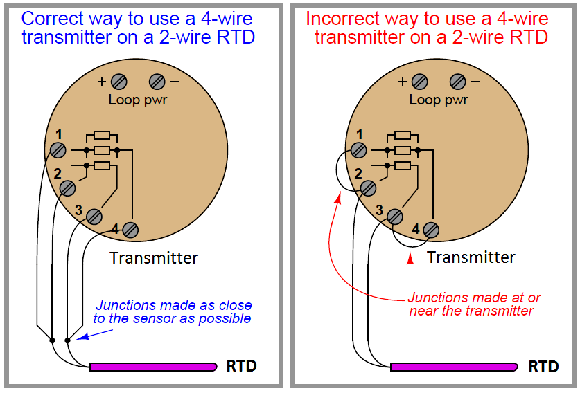
Jumpers placed at the transmitter terminals defeat the purpose of the transmitter’s 3-wire or 4-wire capabilities, downgrading its performance to that of a 2-wire system.
A similar problem occurs when someone tries to connect a 3-wire RTD to a 3-wire transmitter using a conveniently available 4-wire cable:
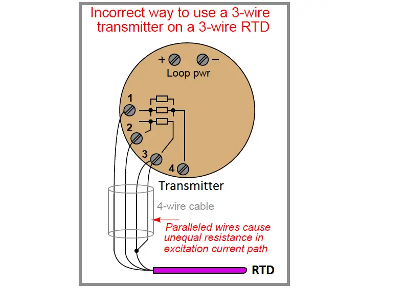
3-wire RTD measurement is based on the assumption that both current-carrying wires have exactly the same electrical resistance. By paralleling two of the four wires in the 4-wire cable, you will create unequal resistances in the current path, thus leading to measurement errors at the transmitter (Note).
Note : These errors will result only if the paralleled wires carry current. If the two wires you paralleled happen to join the transmitter’s sensing terminal to the RTD (the one carrying no current), no errors will result.
However, many RTD transmitters do not document which of the terminals sense (carry no current) versus which of them excite (carry current to the RTD), and so there is a probability of getting it wrong if you simply guess.
Given that there is no real benefit to having paralleled wires connecting the transmitter’s sensing terminal to the RTD, my advice is to either use all four wires and configure the transmitter for 4-wire mode, or don’t use the fourth wire at all.
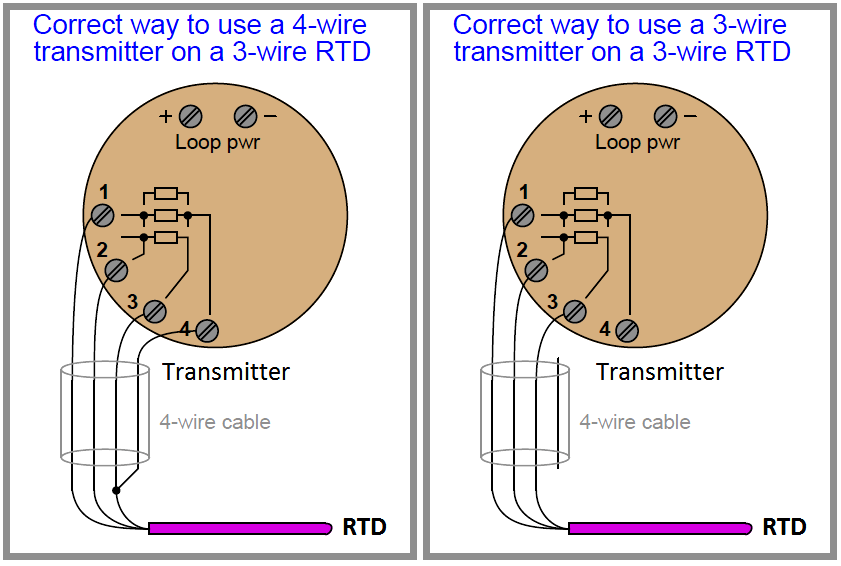
Better solutions for the 3-wire RTD and 4-wire cable scenario include configuring the transmitter for 4-wire RTD input and actually using all four terminals (shown on left), or keeping the transmitter configured for 3-wire RTD input and not using the fourth wire in the cable at all (shown on right):
A photograph of a modern temperature transmitter capable of receiving input from 2-wire, 3- wire, or 4-wire RTDs (as well as thermocouples, another type of temperature sensor entirely) shows the connection points and the labeling describing how the sensor is to be connected to the appropriate terminals:
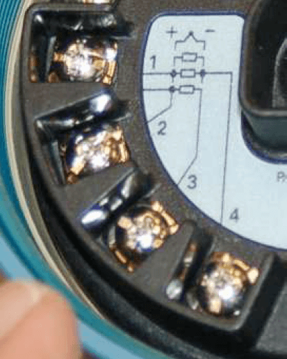
The rectangle symbol shown on the label represents the resistive element of the RTD. The symbol with the “+” and “−” marks represents a thermocouple junction, and may be ignored for the purposes of this discussion.
As shown by the diagram, a two-wire RTD would connect between terminals 2 and 3. Likewise, a three-wire RTD would connect to terminals 1, 2, and 3 (with terminals 1 and 2 being the points of connection for the two common wires of the RTD). Finally, a four-wire RTD would connect to terminals 1, 2, 3, and 4 (terminals 1 and 2 being common, and terminals 3 and 4 being common, at the RTD).
Once the RTD has been connected to the appropriate terminals of the temperature transmitter, the transmitter needs to be electronically configured for that type of RTD.
In the case of this particular temperature transmitter, the configuration is performed using a “smart” communicator device using the HART digital protocol to access the transmitter’s microprocessor-based settings. Here, the technician would configure the transmitter for 2-wire, 3-wire, or 4-wire RTD connection.
Credits : Tony R. Kuphaldt – Creative Commons Attribution 4.0 License


Thank you sir for your valuable information and I am requesting you to please upload gas analyzers, Water analyzers and lab instruments related articles and operating principles.
Best regards
Thanks for Your Valuable Suggestion We are using 4- Way Connection for RTD Transmitter for 4- Wire cable ,You have given Very Clearly Understanding & helpful To our Daily Practice in oil & gas Petrochemical & Refinery use ,
Thanks sir for your valuable information. I would like to know how the connection between the RTD – 4wire connected from the motor RTD junction box to the switchgear protection relay i.e. to which terminals, what type of cable, how many cores required,.etc.
I would appreciate if you clarify how the customer connect the RTD transmittal to the switchgear and what type of cable required and how many cable triad needed for 4 wires RTD. if you can show interconnection diagram will be appreciated
I want to see the connection of 3 wire RTD connected to a wheatstone bridge & then connected to a 2 wire transmitter to a PLC.All the pictures that are available online either shows only a connection between RTD & wheatstone bridge or they show the overview of a transmitter with the connection points the way you have showed in the current post