An error is a condition that occurs when the receiver’s information does not match the sender’s information. During transmission, because of noise, errors can be introduced in the binary bits of the digital signals that are traveling from the sender to the receiver.
This means that the bits may change; for example, a 0 bit may change to 1 or vice versa. Data that is implemented at either the data link layer (layer 2) or the transport layer (layer 4) can get scrambled by noise. The data may also get corrupted when a message is transmitted.
Serial Communication Error Checking Methods
To prevent such errors in the data, some extra bits are added to the digital messages and are called error detection codes. The error detection codes help in detecting errors that may have occurred during the message transmission.
Error detection methods are usually performed at both the sender’s and receiver’s ends of serial transmission.
Types of Errors in Serial Communication
The different types of errors in serial communication are:
- Single-bit error: In a single-bit error, only one bit is altered, which results in an incorrect or corrupted data unit.
- Multiple-bit error: In a multiple-bit error, more than one bit is altered during transmission.
- Burst error: In burst errors, several consecutive bits are altered during transmission.
Some methods and algorithms for error checking for serial communication are:
- Parity bit check
- Checksum error check
- Cyclic Redundancy Check (CRC)
Parity Bit Check
Parity bit checking is the simplest form of error detection. In parity bit checking, a single bit is added to the end of the transmitted data for the purpose of error detection. The parity error-checking method can be used only for detecting errors and cannot correct them.
For the parity error check to work properly, there must be an odd number of errors. This is because if there are even a number of errors, they will cancel out any change in the parity bit summation.
Parity error checking can be odd or even. For checking parity, only the ‘1’s in the byte are counted (including the parity bit).
Even Parity Check
In the case of an even parity check, the total number of 1’s must be even. The parity bit in such a case is zero. If the number of 1’s is odd, the parity bit is 1, and vice versa.
Example:
- 1001010
In this data, there are three 1’s. Thus, the number of 1’s is odd, and the parity bit that needs to be added will be ‘1’. Hence, the data would be 10010101.
- 1010101
In this data, there are four 1’s. Thus, the number of 1’s is even, and the parity bit that needs to be added will be ‘0’. Hence, the data would be 10101010.
Odd Parity Check
In the case of an odd parity check, the total number of 1’s must be odd. The parity bit in such a case is zero. If the number of 1’s is odd, the parity bit is 0, and vice versa.
Examples:
- 1001010
In this data, there are three 1’s. Thus, the number of 1’s is odd, and the parity bit that needs to be added will be ‘0’. Hence, the data would be 10010100.
- 1000111
In this data, there are four 1’s. Thus, the number of 1’s is even, and the parity bit that needs to be added will be ‘1’. Hence, the data would be 10001111.
The data at the sender’s and receiver’s ends is checked for parity, and errors are detected.
Two-Dimensional Parity Check
In the two-dimensional parity check, the parity bits are calculated for each row. This is equivalent to a simple parity check bit.
Parity check bits need to be calculated for each column. After this, both the party bits are sent along with the data. On the receiving end, both the parity bits are compared with the parity bits that are calculated on the received data.
Let’s assume the data below. Also, let us assume even parity checking.
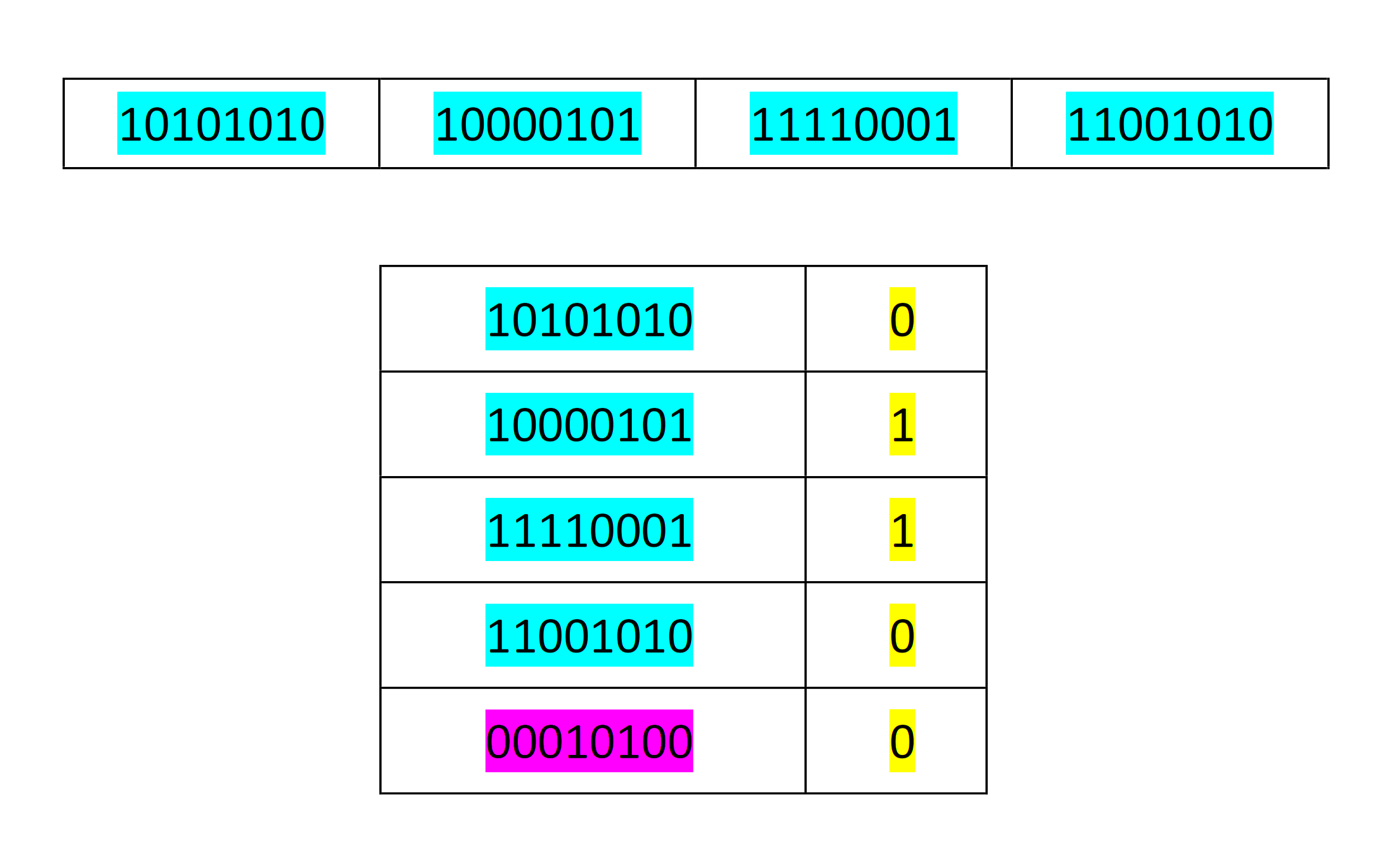
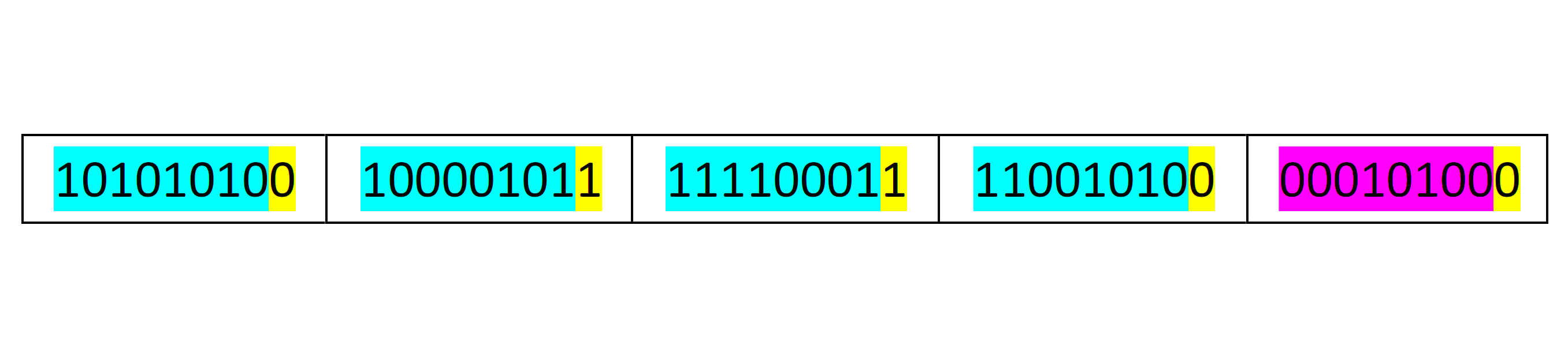
So, the data that is to be transmitted will have an extra byte for the column parity. The final data to be transmitted is shown below.
Advantages of the Parity Check Error Detection Method
- The parity check method is the simplest form of error detection.
- The parity check method is easy to use.
- The parity check method can be enhanced with the use of other advanced detection methods like cyclic redundancy checks or forward error correction.
Disadvantages of the Parity Check Error Detection Method
- A single parity check cannot detect an even number of bit errors.
- Sometimes, parity checks can result in false errors.
- Parity checking cannot detect which bit of the code has an error.
Checksum Method of Error Detection
The checksum method of error detection is complex as compared to the parity check method. The checksum method of error detection has a higher degree of precision and fewer chances of a missed error.
In the process of error detection, the data is divided into equally-sized segments. Then the sending unit creates a checksum by adding the bits using 1’s complement arithmetic. If there is a carry-over digit in the 1’s complement, it is added to the sum.
Hence, the length of the sent data sequence will remain the same. All of the data is added, and then the sum is complemented to create a checksum. In terms of Boolean, complement means changing all 0’s to 1’s and vice versa. At the sender’s end, the checksum is sent with the data.
At the receiver’s end, the summation of the data is performed. This summation is then added to the checksum. Later, the final complement of the last summation is performed. If there are no errors in the data, the resulting summation complement is always zero.
Examples:
| 10101010 | 10000101 | 11110001 | 11001010 |
At the sender’s end:
Adding the first two segments using 1’s complement arithmetic: 10101010 and 10000101, the resulting sum will be 100101111. But here there is an MSB bit with carry. So the carry will be added to the sum so as to keep the number of digits constant. Hence, the final sum of the first two segments of data is 00110000.
In the next step, the sum of the first two segments will be added to the third segment’s data, i.e., 00110000 and 11110001. Hence, the resulting sum will be 100100001. Again, there is a carry bit. So, adding the carry bit to the sum, we get 00100010.
In the next step, the sum is added to the fourth segment’s data, i.e., 00100010 and 11001010. The resulting sum will be 11101110.
The sum should then be complemented to get the checksum. Hence, the checksum here is 00010001.
The sent data is:
| 10101010 | 10000101 | 11110001 | 11001010 | 00010001 |
At the receiver’s end:
All the received segments need to be added using 1’s complement arithmetic. So, adding the first two segments, 10101010 and 10000101, we get the sum as 100101111. Here also, we add the carry bit, so we get 00110000.
In the next step, the sum of the first two segments is added to the third segment’s data, i.e., 00110000 and 11110001. Hence, the resulting sum will be 100100001. Again, there is a carry bit. So, adding the carry bit to the sum, we get 00100010.
In the next step, the sum is added to the fourth segment’s data, i.e., 00100010 and 11001010. The resulting sum will be 11101110.
In the next step, the sum is added to the fifth segment’s data, i.e., 11101110 and 00010001. The resulting sum will be 11111111.
The complement of the sum will be 00000000. Hence, the received data has no errors.
Advantages of the Checksum Method of Error Detection
- The checksum method of error detection is easy to implement.
- The checksum codes can be computed very quickly, which makes them suitable for real-time data packet transmissions.
- The checksum method of error detection has very low latency.
Disadvantages of the Checksum Method of Error Detection
- The checksum method of error detection is able to detect common errors only.
- The checksum method of error detection can only detect errors; it cannot correct them.
- If one or more bits of a segment are damaged, the corresponding bits of the opposite value in the second segment are also damaged.
Cyclic Redundancy Check (CRC)
The cyclic redundancy check method of error detection makes use of polynomial division. The cyclic redundancy check method of error detection not only checks the number of 1’s and 0’s but also checks if the order is correct or not.
In the cyclic redundancy check method, the data to be checked is treated like a polynomial equation. The equation is then divided by a chosen divisor. The value of the divisor is essential for deciding the accuracy and usefulness of the cyclic redundancy check.
The binary information must be converted into a polynomial equation so as to fit the check method. To do this, the binary numbers become the coefficients of the polynomial expression. The length of the polynomial expression matches the length of the code to be divided.
In the CRC, a sequence of redundant bits is appended at the end of the data unit. The sequence of redundant bits is called cyclic redundancy check bits. By appending these bits, the resulting data becomes exactly divisible by a predetermined binary number.
At the receiver’s end, the data is divided by the same number. If the remainder is zero, the data is assumed to be correct and is accepted.
If the remainder is non-zero, it indicates that the data is damaged and must be rejected.
Example:
Let us assume the data is 1010000.
The polynomial would be
x6 + 0x5+ x4+ 0x3+ 0x2+ 0x + 0
Let us assume another polynomial, or the key with which we would divide the equation, is 1001. Hence, the equation would be
x3+ 0x2+ 0x + 1
Now, the division is performed, and the remainder is found. The remainder is then appended to the data that is to be transmitted. The division is performed using XOR division.
The received data is also divided by the key. If the difference between the remainder at the receiver’s end and that of the sender’s end is zero, the data is not corrupt. If the difference is non-zero, there is some damage to the data transmitted.
Calculation at the sender’s end
Data to be transmitted (actual data): 1010000
Dividend = actual data + (number of bits in key – 1)
So, in this case, the dividend = 1010000000
Divisor (key) = 1001
1010000000 ÷ 1001 = 0011
So, the remainder 0011 must be appended at the end of the actual data, i.e., 1010000011.
Hence, the message sent to the receiver is
Actual data: 1010000
Key: 1001
Code word: 1010000011
Calculation at the receiver’s end
The receiver will divide the code word by the key. If the remainder is zero, the data is trusted to be correct. If the remainder is non-zero, it means the data is damaged.
If you liked this article, then please subscribe to our YouTube Channel for Electrical, Electronics, Instrumentation, PLC, and SCADA video tutorials.
You can also follow us on Facebook and Twitter to receive daily updates.
Read Next:
- What is a Dry Contact?
- What is a Wet Contact?
- 4-20 mA Transmitter Wiring
- Why 24 Volts DC Power Supply?
- Interposing Relay Panel Wiring