Inst ToolsInst ToolsInst Tools
  • Courses
  • Automation
    • PLC
    • Control System
    • Safety System
    • Communication
    • Fire & Gas System
  • Instrumentation
    • Design
    • Pressure
    • Temperature
    • Flow
    • Level
    • Vibration
    • Analyzer
    • Control Valve
    • Switch
    • Calibration
    • Erection & Commissioning
  • Interview
    • Instrumentation
    • Electrical
    • Electronics
    • Practical
  • Q&A
    • Instrumentation
    • Control System
    • Electrical
    • Electronics
    • Analog Electronics
    • Digital Electronics
    • Power Electronics
    • Microprocessor
  • Request
Search
  • Books
  • Software
  • Projects
  • Process
  • Tools
  • Basics
  • Formula
  • Power Plant
  • Root Cause Analysis
  • Electrical Basics
  • Animation
  • Standards
  • 4-20 mA Course
  • Siemens PLC Course
Reading: Loop Calibrator to Simulate a 4-20 mA Signal
Share
Notification Show More
Font ResizerAa
Inst ToolsInst Tools
Font ResizerAa
  • Courses
  • Design
  • PLC
  • Interview
  • Control System
Search
  • Courses
  • Automation
    • PLC
    • Control System
    • Safety System
    • Communication
    • Fire & Gas System
  • Instrumentation
    • Design
    • Pressure
    • Temperature
    • Flow
    • Level
    • Vibration
    • Analyzer
    • Control Valve
    • Switch
    • Calibration
    • Erection & Commissioning
  • Interview
    • Instrumentation
    • Electrical
    • Electronics
    • Practical
  • Q&A
    • Instrumentation
    • Control System
    • Electrical
    • Electronics
    • Analog Electronics
    • Digital Electronics
    • Power Electronics
    • Microprocessor
  • Request
Follow US
All rights reserved. Reproduction in whole or in part without written permission is prohibited.
Inst Tools > Blog > Control Systems > Loop Calibrator to Simulate a 4-20 mA Signal

Loop Calibrator to Simulate a 4-20 mA Signal

Last updated: February 21, 2020 10:22 am
Editorial Staff
Control Systems
2 Comments
Share
1 Min Read
SHARE

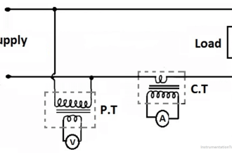
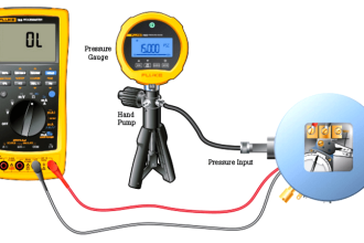
Suppose a technician wishes to use a loop calibrator to simulate a 4-20 mA signal to a controller, and decides to connect the loop calibrator to the circuit like this:

Loop Calibrator to Simulate a 4-20 mA Signal

Loop Calibrator to Simulate a 4-20 mA Signal

Explain why this is an improper use of the loop calibrator, and what will happen if the technician tries to simulate a 9 mA signal this way. Finally, identify the proper way to use the loop calibrator to simulate a transmitter signal.

Share your answers with us through comments.

Read Next:

  • How to use Loop Calibrator
  • 4–20 mA Control Loops
  • As-Found and As-Left
  • Loop Powered Instruments
  • Loop Checks Transmitters

Credits: Tony R. Kuphaldt

Don't Miss Our Updates
Be the first to get exclusive content straight to your email.
We promise not to spam you. You can unsubscribe at any time.
Invalid email address
You've successfully subscribed !

Continue Reading

Control Valve Split Range Example
Industrial Automation in the Mining Industry
Power Factor Controller (PFC) – Commissioning
Types of Industrial Control Systems
Identify Faults in PID Control Loop
VFD Simulator Download – Free Yaskawa V1000 Software
Share This Article
Facebook Whatsapp Whatsapp LinkedIn Copy Link
Share
2 Comments
  • saurav kumar gupta says:
    February 13, 2020 at 10:36 am

    The calibrator is not even in closed loop and it is connected as a parallel dc source which will add more mili amps to the instrument additional to the controller mamps supply. Thus the operation of the instrument will be not as expected.

    Reply
  • Vignesh says:
    March 23, 2020 at 1:29 pm

    Once we have simulate the mA values to the DCS with probes directly to the 24v dc cores without the connection in the tx.

    Reply

Leave a Reply Cancel reply

Your email address will not be published. Required fields are marked *

Stay Connected

128.3kFollowersLike
69.1kFollowersFollow
210kSubscribersSubscribe
38kFollowersFollow

Categories

Explore More

Relation Control System
Difference Between PNP and NPN Sensors
Most Asked Questions on SCADA with Answers
Temperature Controller Problem
What is Instrumentation Control System ?
Grounding of Telecommunication Systems
What are Analog and Digital Signals? Differences, Examples
What is a Control Loop ?

Keep Learning

Key Facts About RS485 Industrial Network

Key Facts About RS485 Industrial Network

how-a-4-20ma-transmitter-works

How a 4-20mA Transmitter Works?

System Architecture in Industrial Automation

How to Design a System Architecture in Industrial Automation?

How to Design a Motor Faceplate in Graphics - SCADA Tutorials

How to Design a Motor Faceplate in Graphics? – SCADA Tutorials

Stripping tower unit

Process Control High Level Alarm Fault Analysis

Three Element Drum Level Control System

Three Element Drum Level Control System

PID-Controller-Selection

PID Controller Selection

Annunciator Panel

What is a Annunciator Panel?

Learn More

Digital Electronics Multiple Choice Questions

Asynchronous Down Counter Objective Questions

Light Tower in Industrial Automation

What is a Tower Lamp? – Light Tower in Industrial Automation

Electrical Machines Questions and Answers

DC Machines Efficiency and Testing Quiz

Electronic Symbols List

Electronic Symbols

PLC Programming for Pumping and Draining System

PLC Programming for Pumping and Draining System

Grounding Components

Selection of Components Used In Electrical Earthing or Grounding

Conveyor Sorting Machine PLC Program

Conveyor Sorting Machine PLC Program with Calculation Function

Water Cut Meter

What is Water Cut Meter?

Menu

  • About
  • Privacy Policy
  • Copyright

Quick Links

  • Learn PLC
  • Helping Hand
  • Part Time Job

YouTube Subscribe

Follow US
All rights reserved. Reproduction in whole or in part without written permission is prohibited.
Welcome Back!

Sign in to your account

Username or Email Address
Password

Lost your password?