In this article, you will learn the general specification and classifications of power electronic devices and various switching devices.
Introduction to Various Semiconductor device
The performance of power circuits is mainly dictated by the ratings of the power devices necessary for circuit operation, it is critical to understand the restrictions posed by the various power devices available and to select the proper device for the desired area of application.
Electrical and thermal properties are the fundamental issues of any semiconductor device characteristics and ratings. Thermal characteristics and cooling design considerations are common to all power-switching semiconductor devices. This virtual junction is regarded as the point source of all losses, including on-state and off-state losses, switch-on and switch-off losses, and any control input loss.
Power Semiconductor Devices
A Power Semiconductor device is a High voltage/current semiconductor device that acts as a switching device between the input and output. It switches between the stages and produces the required output to the load (AC/DC).
General Specification of Power Electronics Devices
The properties of practical semiconductor devices differ from those of an ideal device. The device makers provide data sheets that describe the device specifications and ratings.
There are several parameters that are critical to the devices.
The most significant of them are as follows.
- Voltage Ratings: Forward and reverse repeating peak voltages, as well as an on-state forward voltage drop.
- Current ratings: Average, root-mean-square (rms), repeating peak, non-repetitive peak, and off-state leakage currents.
- Switching speed or frequency: The transition from a fully non-conducting to a fully conducting state (turn-on) and the transition from a fully conducting to a fully non-conducting state (turn-off) are critical characteristics.
- di/dt rating: The device requires just a small amount of time until its entire conducting surface is used for carrying the full current. If the current rapidly rises, the current flow may be concentrated in a specific place, causing the device to be destroyed. Normally, the di/dt of the current through the device is restricted by connecting a small inductor in series with the device, which is referred to as a series snubber.
- dv/dt rating: Cj is the internal junction capacitance of a semiconductor device. If the voltage across the switch changes fast during turn-on and turn-off, as well as while connecting to the main supply, the initial current, Cj dv/dt flowing through Cj, may be abnormally high, causing device damage. The voltage across the device’s dv/dt is restricted by attaching an RC circuit across it, known as a shunt snubber, or simply snubber.
- Safe operating area (SOA): The quantity of heat produced by the device is proportional to the power loss, i.e., the voltage-current product. The current must be inversely proportional to the voltage in order for this product to be constant P = vi and equal to the highest permitted value. In the voltage-current coordinates, this gives the SOA limit on the allowed steady-state operating points.
- Temperatures: Maximum permissible junction, case, and storage temperatures, typically between 150°C and 200°C for junction and case, and between -50°C and 175°C for storage.
- Thermal resistance: Junction-to-case thermal resistance (Qjc), case-to-sink thermal resistance (QCS), and sink-ambient thermal resistance (QsA). Power dissipation must be dissipated quickly from the internal wafer to the packaging and eventually to the cooling media. The size of semiconductor power switches is limited to 150 mm, and the thermal capacity of a bare device is insufficient to safely remove the heat created by internal losses. Heat sinks are commonly used to install power equipment. As a result, removing heat has a significant equipment cost.
Classification of Power Electronic Devices

Fig 1. Classification of Power Semiconductor devices
Most semiconductors are used as switching devices whether the semiconductor device is a low-voltage or high-voltage device. The Semiconductor device is classified into two, Three, and Multi-terminal devices.
Two Terminal Devices
The diodes are examples of two terminal devices, such as
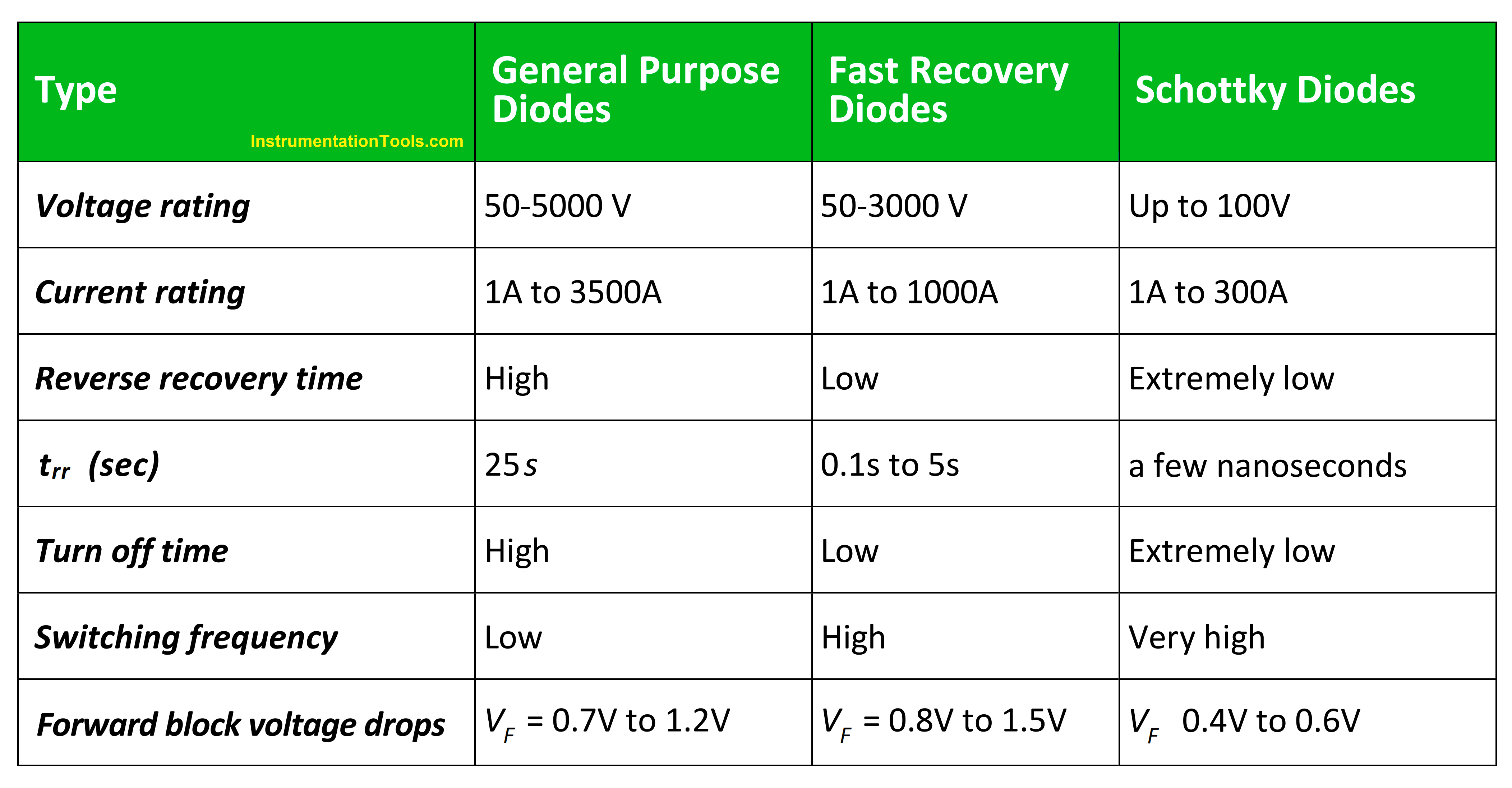
- General Purpose Diodes
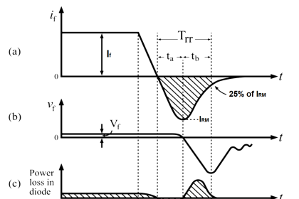
- Fast Recovery Diodes
- Schottky Diodes
Three Terminal Device
The following are the three-terminal devices.
- BJT
- MOSFET
- IGBT
- GTO
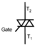
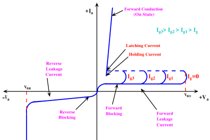
- SCR
- RCT
- IGCT
- SITH
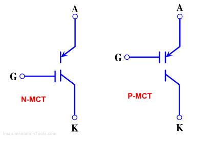
- MCT, etc.
Multi Terminal Device
The multi-terminal devices such as Intelligent Power Module (IPM) are examples.
Comparison between different types of diodes
Comparison between three Terminal Devices
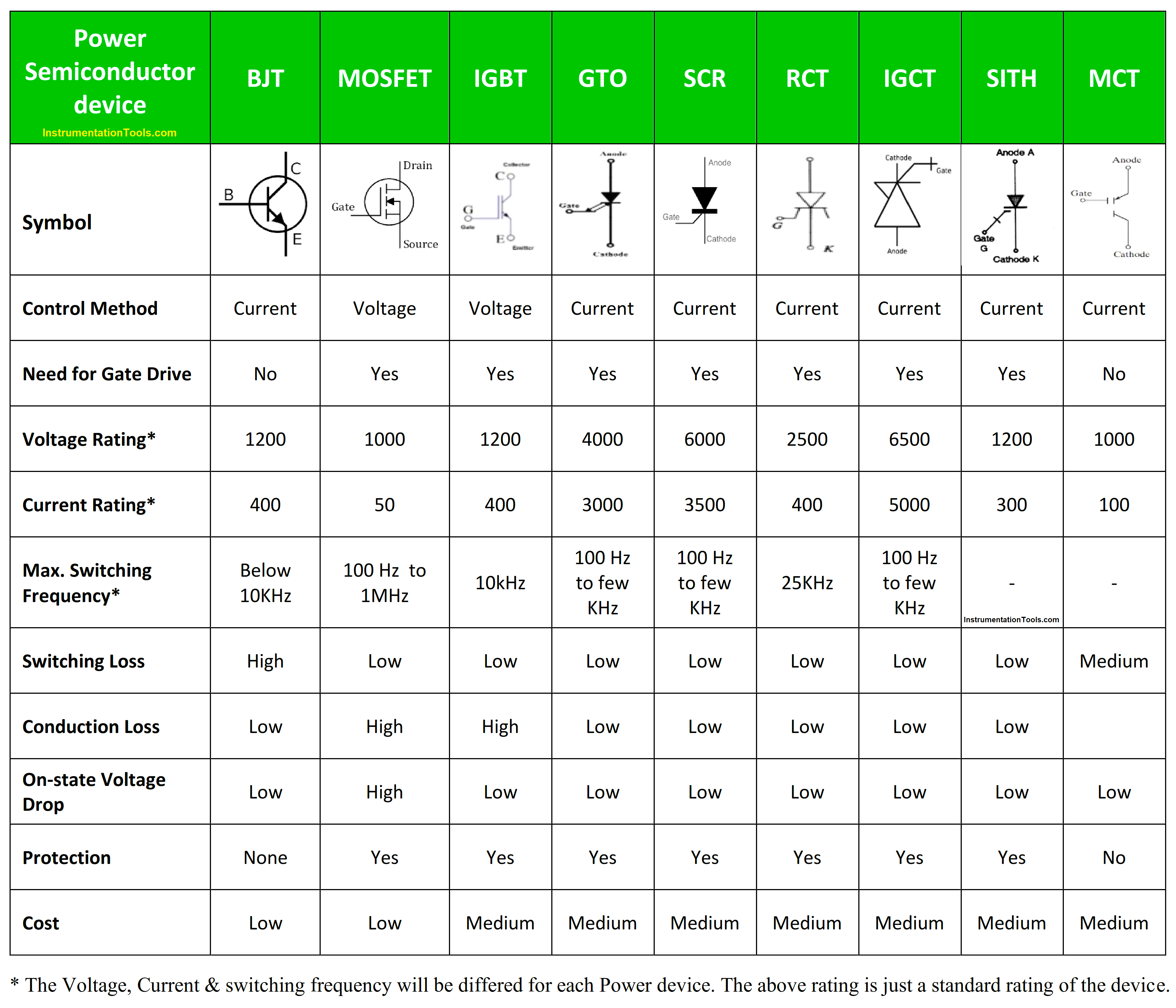
The Voltage, Current & switching frequency will be different for each Power device. The above rating is just a standard rating of the device.
Intelligent Power Module (IPM)
Intelligent power modules are primarily targeted at the high-voltage sector. “High” is a relative term; in the language of low-voltage engineers 50 V would be considered “high,” but in the context of IPMs, it’s actually very low.
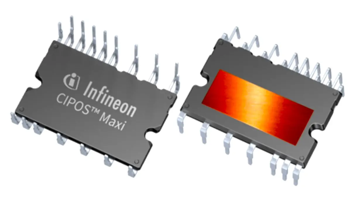
The lowest maximum voltage rating of Infineon’s CIPOS Nano series, for example, is 40 V. The greatest voltage is 600 V, and the Nano line is Infineon’s smallest, lowest-power alternative. The Maxi series can withstand voltages of up to 1200 V and dissipate 50 W per IGBT. The switching frequency for Intelligent Power Module will be up to 20 kHz.
Applications of Intelligent Power Module (IPM)
- Fans, air purifiers, washing machines, air conditioners, refrigerators, and vacuum cleaners are examples of household appliances.
- Pumps, compressors, HVAC, and lifts are examples of industrial equipment.
- AC compressors, oil pumps, and on-board charging in electric vehicles are examples of automotive components.
Thermal Rating of Power Electronic Devices
The power Electronics devices mainly concern with higher voltage and current ratings. Since the power semiconductor devices handle with higher current ratings the device has high intensity of electron movement, which causes higher temperature variation it leads to high junction temperature cause damage of damage. So, most of the power electronic devices requires cooling like heat sink, etc.
The maximum permitted junction temperature Tj is determined by the quality of the materials used and the kind of junction, and it is balanced against the lower dependability and accelerated service life caused by degradation. The faster the junction temperature rises, the faster it deteriorates. The equation approximates the link between service life Lt in hours and junction temperature Tj (K).
Log10 Lt = (A+ B) / Tj
where A and B are constants relating to the device type
The power dissipated in a semiconductor device is transformed into thermal energy, causing the temperature to increase. The maximum permitted junction temperature and device case temperature Tc are the key criteria limiting the maximum allowable power dissipation Pd. According to, these factors are connected by the thermal resistance Rθ.
Pd = (Tj – Tc) / Rθ
Thermal resistance at the virtual junction Rθ is a physical parameter that represents the junction temperature rise per unit power dissipation ratio. Thermal resistance quantifies the difficulty of transferring heat from the junction to the casing. Most maximum power values are set at 25°C and derated linearly to zero when the case-operating temperature rises to Tj, which is generally 175°C and 200°C for silicon and silicon carbide power devices, respectively.
If you liked this article, then please subscribe to our YouTube Channel for Instrumentation, Electrical, PLC, and SCADA video tutorials.
You can also follow us on Facebook and Twitter to receive daily updates.
Read Next:
- What is Power Electronics?
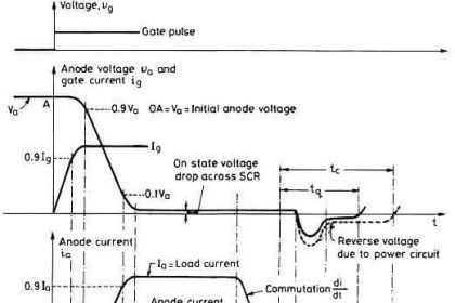
- SCR Switching Characteristics
- Thyristor Interview Questions
- Power Diode Characteristics
- Power Transistor Structure & Biasing