This article is about Controlling two motors in a sequential manner. The purpose of the sequential control is to maintain the predetermined order at which the motors are forced to stop or start.
Nowadays, most applications use two motors for operation. But the major thing is they need not to be activated at a time, Motors need to start after some interval. i.e., sequential control after some delay. So, this sequential control comes in for action.
We use an ON delay timer in this sequential control. The timer makes control automatically without any manual help. This saves Manual operation and Timer control is one of the best and easy methods for automatic sequential control
Simulation
The below video shows the simulation of two motors controlled in sequence with time delay.
Components
- Miniature Circuit Breaker (MCB)
- Contactor
- Timer
- Start and Stop Push Buttons
- Multimeter
- Clampmeter
Circuit Diagrams
This Sequential control of motors has two circuits. They are:
- Power Circuit
- Control Circuit
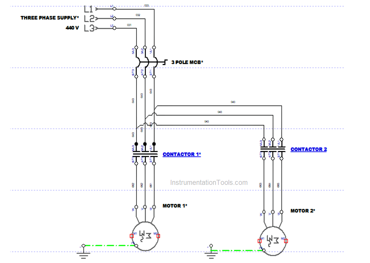
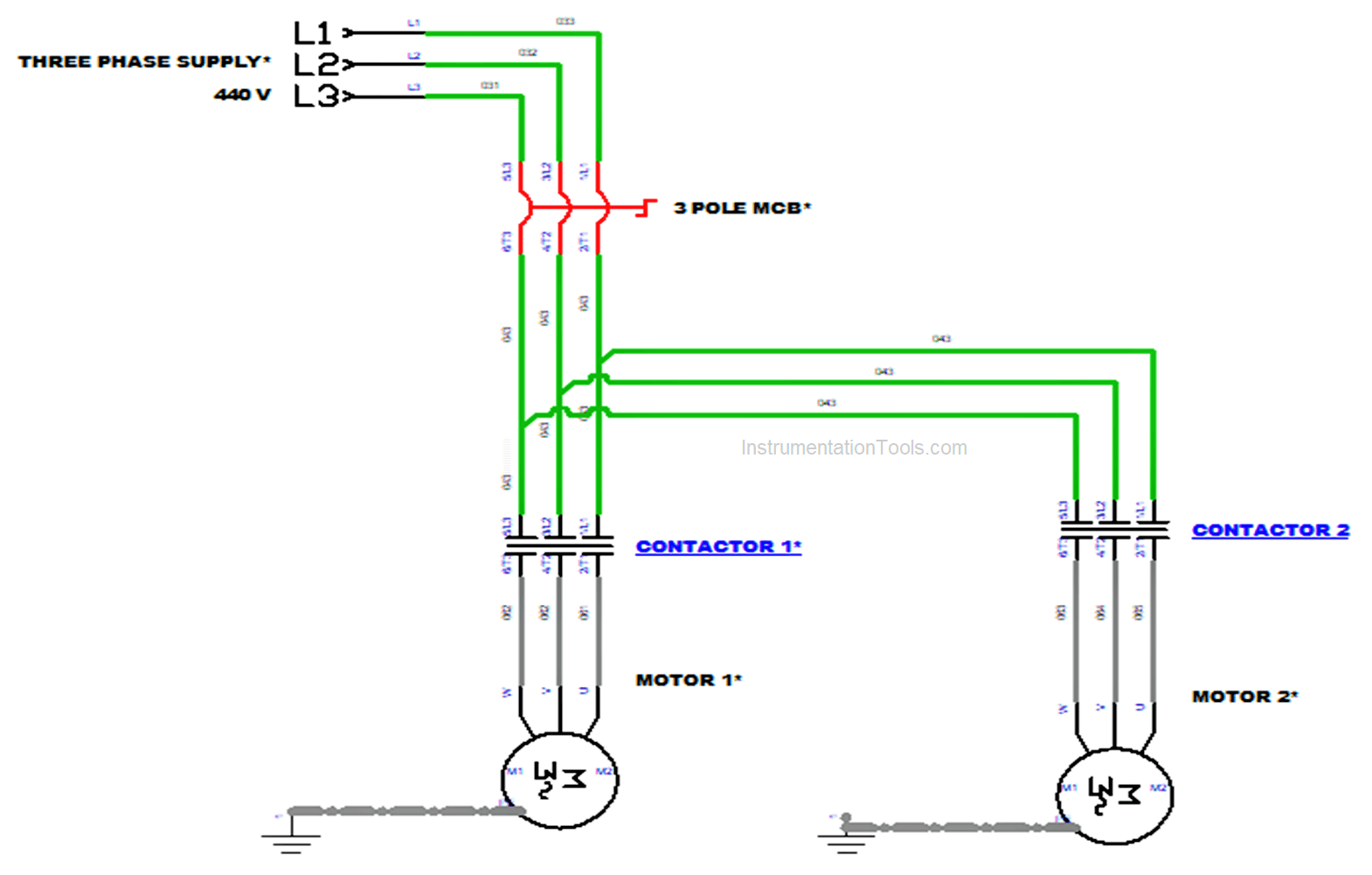
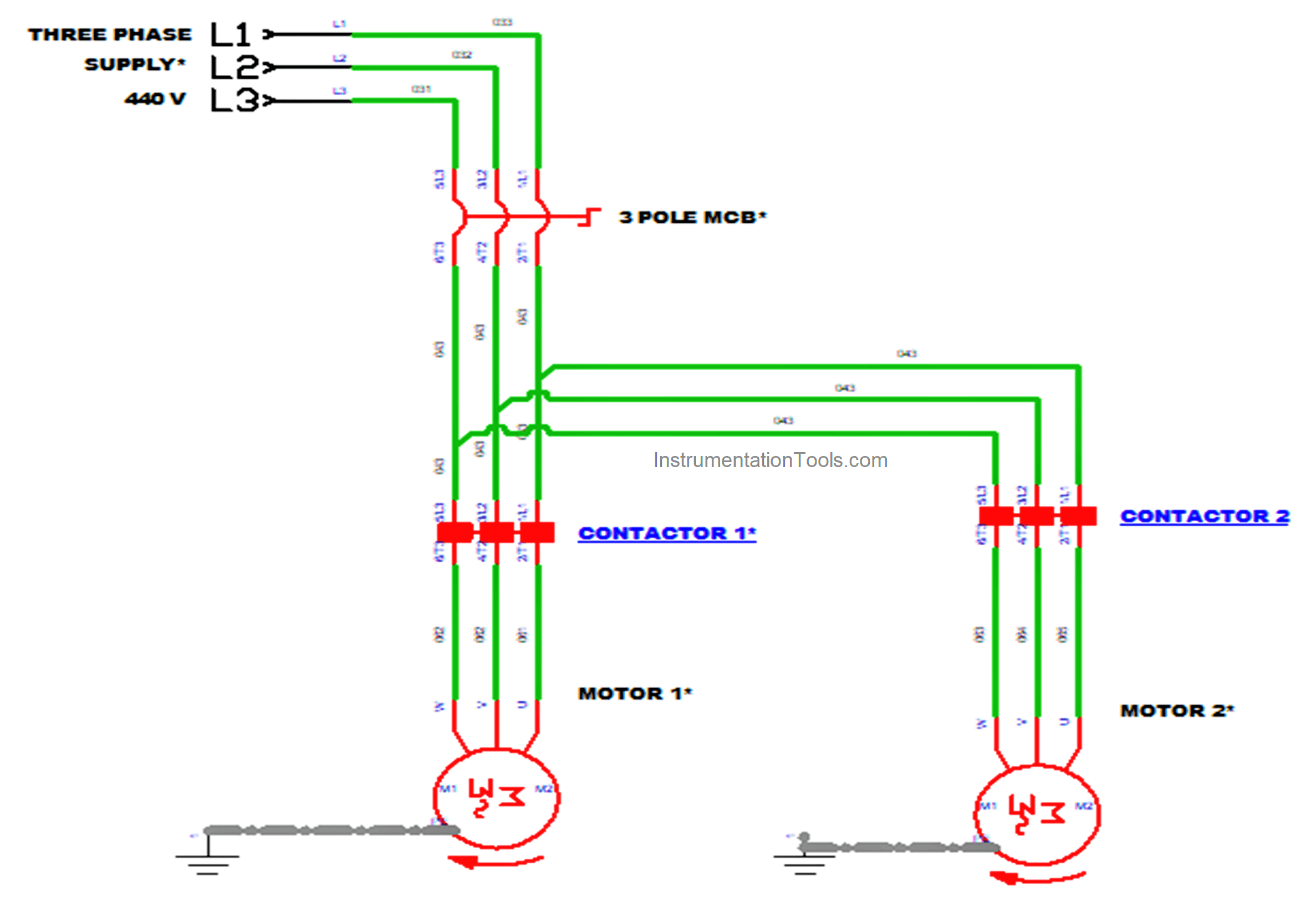
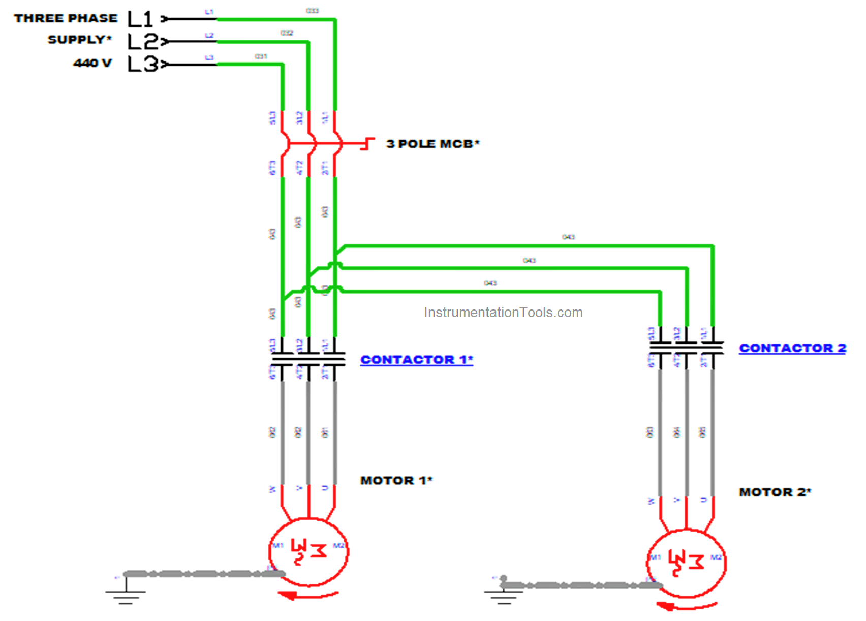
Power Circuit
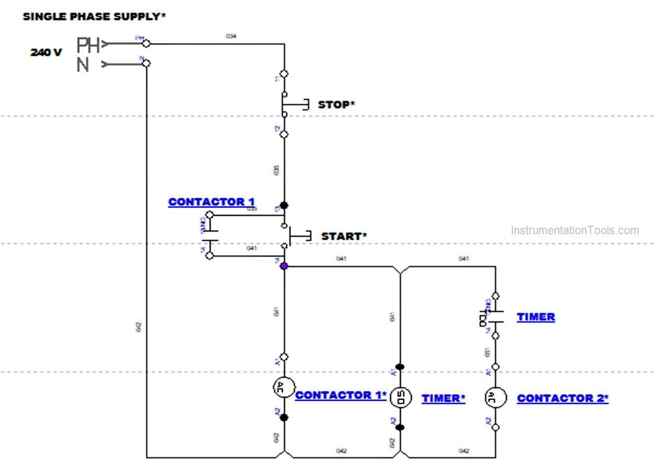
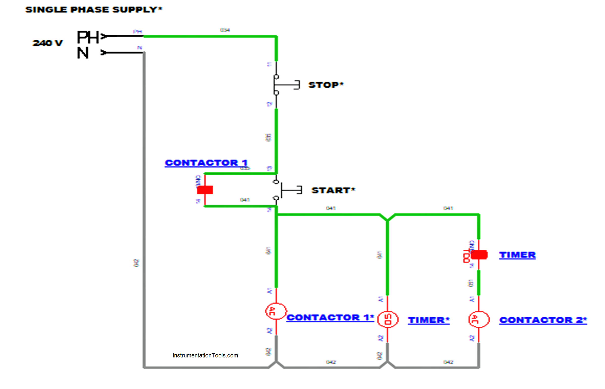
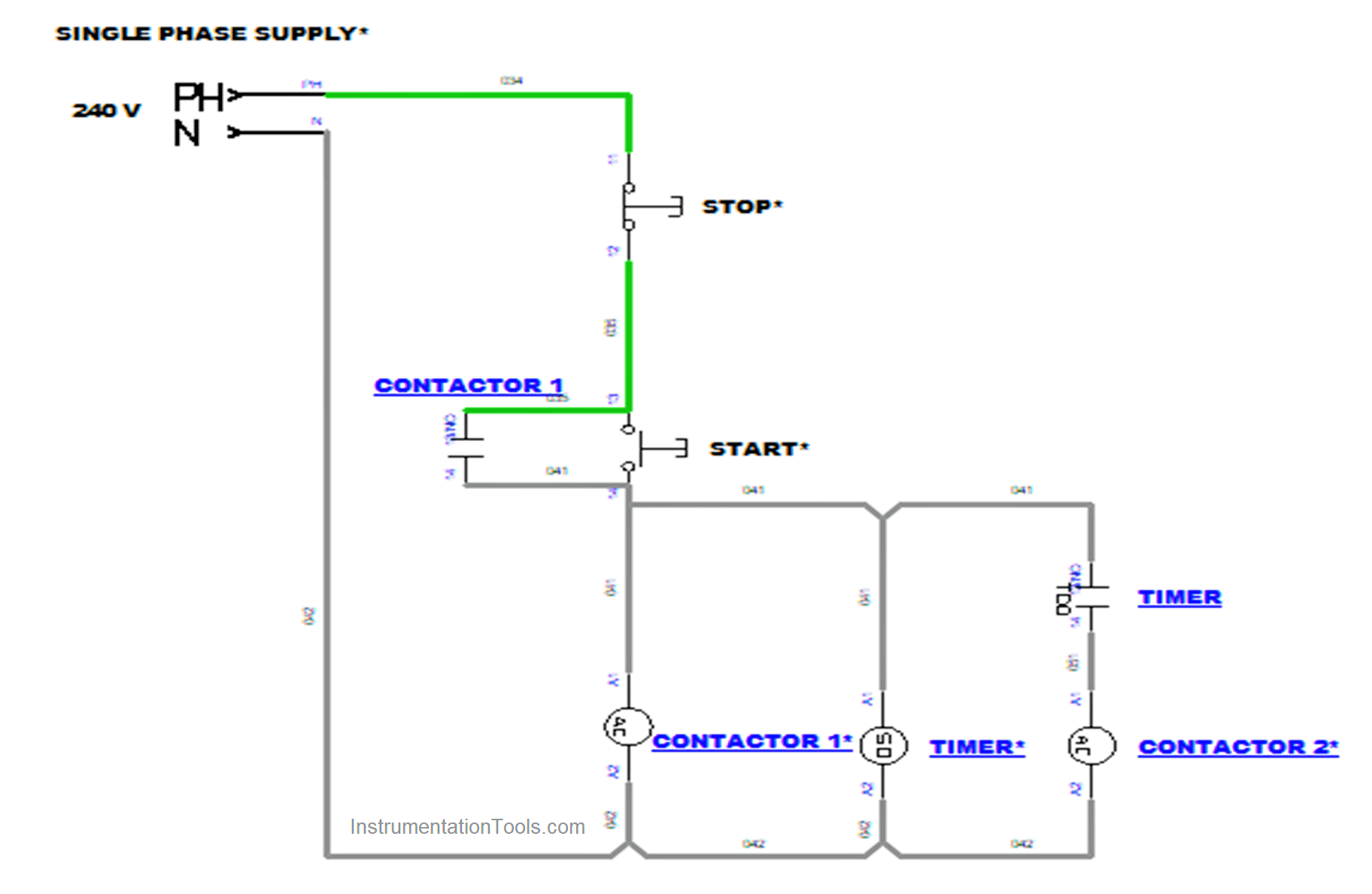
Control Circuit
Operation
Three Phase power supply of 440 V is given to the 3 Pole MCB.
MCB Protects the Overcurrent/ Uneven Voltage which affects the circuit or components.
3 Pole MCB are designed in the case of carrying forward the power supply after switching ON.
Next, a Control supply of 240 V is given to the control circuit. The reason for the Single Phase supply (240 V) used in the control circuit is all the control elements are rated for 240 V.
Here this 240 V is carried through this circuit by passing over the STOP button. After Pressing the START button the supply goes to Contactor 1 coil and Timer coil.
Now Contactor 1 and Timer got energized. Also, the Holding contact for Contactor 1 (NO Contact) is given parallel to the start supply as the Contactor 1 coil and Timer coil needs to be energized after the release of the START button.
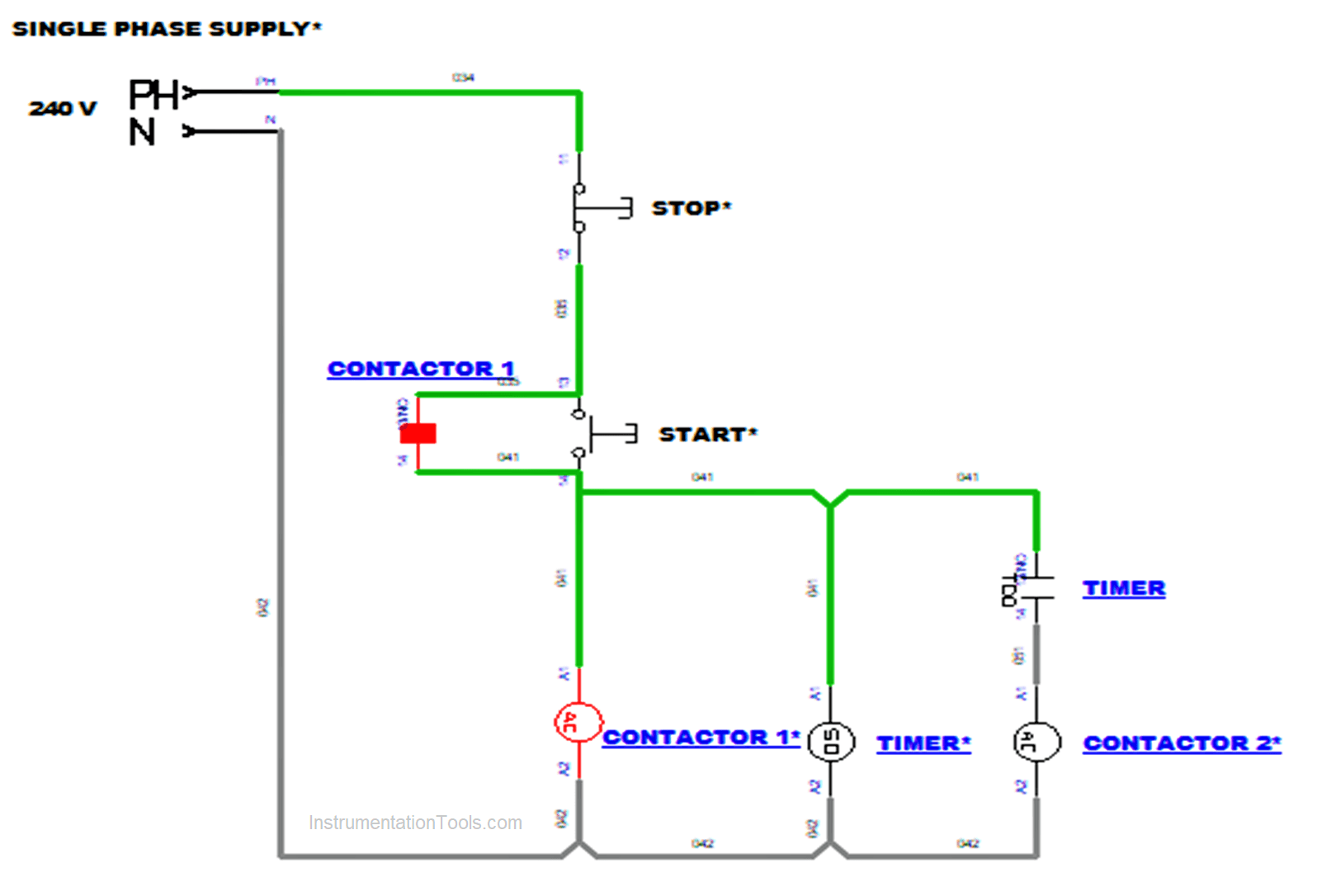
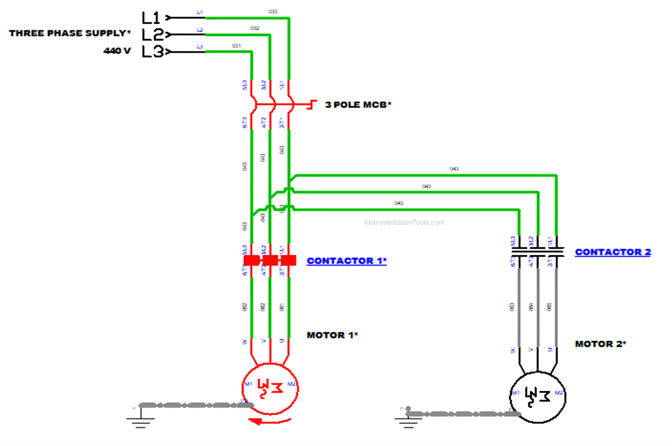
Thus the Contactor 1 coil was energized in the control circuit which makes the Contactor1 close.
Now Contactor 1 was activated and the power supply from the 3 Pole MCB goes to activated Contactor 1 and Motor 1 starts to rotate now.
Here the motor is started with control of the Start button in the control circuit.
Now Motor 1 is running and after some seconds Motor 2 will start. Motor 2 was controlled by Timer. At first Contactor 1 Coil and Timer coil was energized.
In Timer, seconds(time) was started to count after the Timer coil got energized. We set a Pre-set time as our need in the application.
After the Actual time meets the Pre-set time in the Timer, Contactor 2 coil got energized.
The timer’s NO contact gets closed after the actual time which makes the energization of Contactor 2 Coil.
Contactor Coil 2 energizing makes the Contactor 2 close. Three Phase supply from the 3 Pole MCB passes through Contactor 2 making the Motor 2 rotate.
Now after some delay time, Motor 2 is also started to rotate.
Thus, the two motors started sequentially after the certain timing set on the timer.
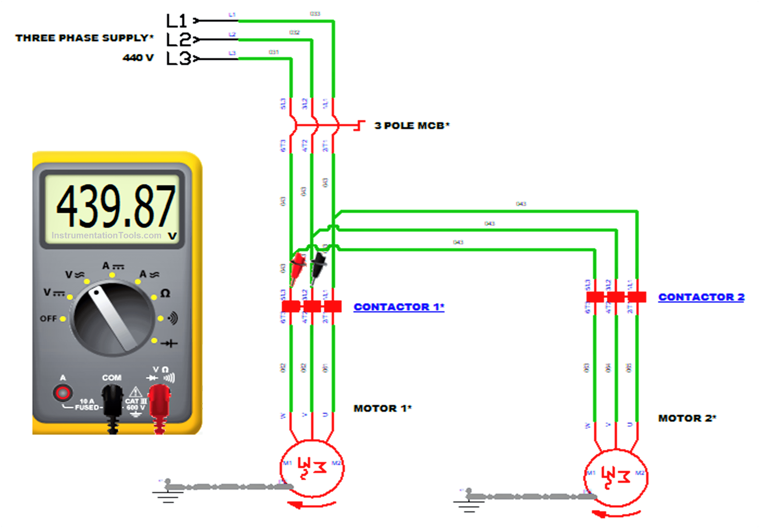
We can also measure the Voltage and Current while the process is going on. Here we use Multi-meter to measure the Voltage.
In Multi-meter, we can measure many parameters like AC Voltage and Current, DC Voltage and Current, Resistance, Continuity like that.
Now we are measuring the AC Voltage, Choose option V~ in Multi-meter. For measuring voltage place two probes of multi-meter in any two lines like L1, L2 or L2, L3 or L1, L3. All show the same values only.
Here two probes are placed in L1 and L2 and the measured voltages were displayed in the display.
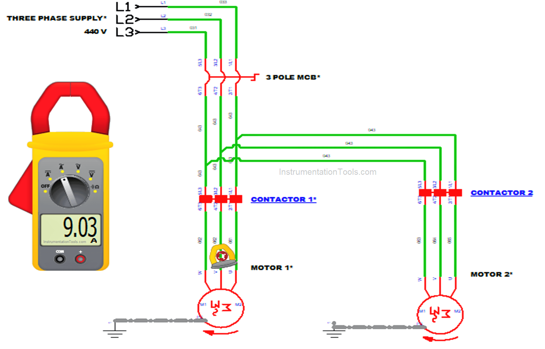
For measuring current we used Clamp-Meter here. The clamp-Meter function is like a Multi-meter only.
We can measure AC Current and Voltage, DC Current and Voltage, resistance, and continuity. The Special function of this meter is, it has a split-core current transformer ( the ring-shaped plier) in this we can measure AC Current without interrupting the circuit.
Measuring current we want to place the clamp in any one of the conductor L1, L2, or L3 at A~ option in clamp-meter. Here we used in L2, the measured current was displayed in the display.
Note: This Clamp meter must work with load only. No-load operation is forbidden here
For stopping the process Stop button is pressed. It makes both Contactor 1 coil, Contactor 2 coil, and timer coil de-energizes.
Because of the de-energizing of Contactor 1 coil and Contactor 2 coil, both contactor 1 and contactor becomes open and the supply for Motor 1 and Motor 2 was stopped.
And Finally, both motor’s rotation was slowly stopped.
Applications
- In Industries, Mixing of two components or products in a tank
- In Agriculture, Water Irrigation in fields automatically.
- In Machineries, for doing various operations one after another
If you liked this article, then please subscribe to our YouTube Channel for Instrumentation, Electrical, PLC, and SCADA video tutorials.
You can also follow us on Facebook and Twitter to receive daily updates.
Read Next: