A single-phase midpoint-controlled rectifier is a rectifier circuit used to convert alternating current (AC) voltage into direct current (DC) voltage. It is called a “midpoint” because it uses a Center-tapped transformer, for controlling.
Semiconductor devices control the rectification process like thyristors or SCRs (Silicon Controlled Rectifiers). This type of rectifier is also known as a single-phase bridge rectifier with a Center tap.
Mid-Point Converter
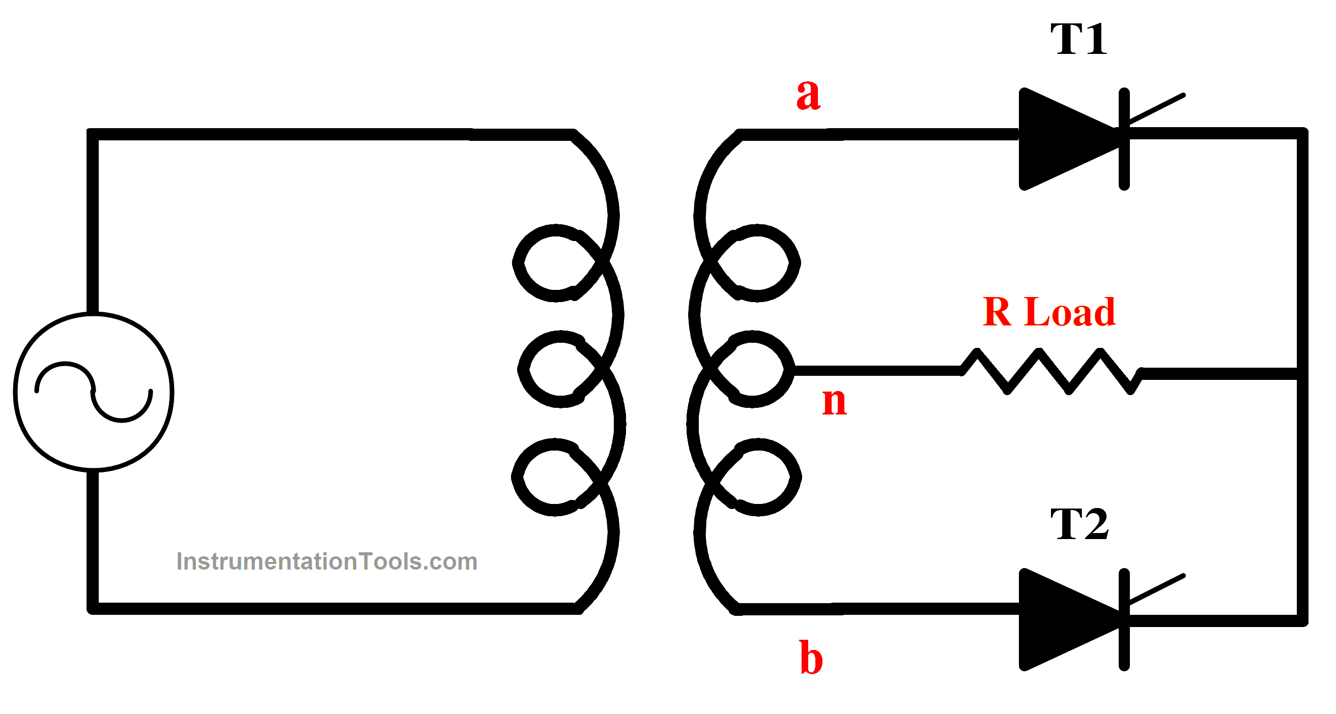
Fig.1.a Single Phase Mid Point Converter With R Load
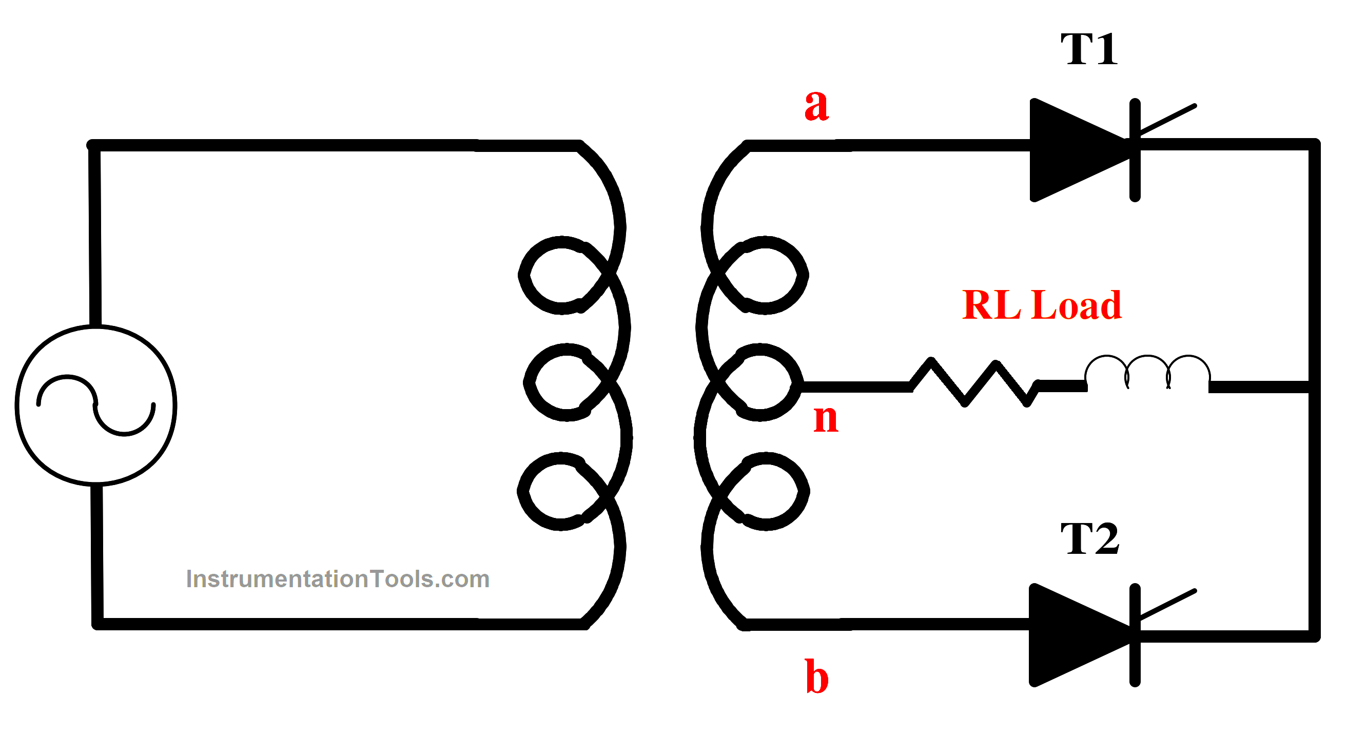
Fig.1.b Single Phase Mid Point Converter With RL Load
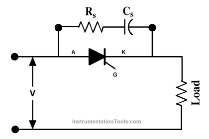
Components of Bridge Rectifier with Center Tap
Center-Tapped Transformer: The primary winding of the transformer is connected to the AC supply, and the secondary winding has a center tap.
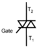
Thyristors (SCRs): Two SCRs are used in this configuration. They are current-controlling semiconductor devices.
Load Resistive(R) or Inductive (RL): The load resistance is connected across the secondary winding of the transformer and provides the output for the rectifier.
Working of Full-Controlled Rectifier R & RL Load
a. Positive Half-Cycle
During the positive half-cycle of the input AC voltage, T1 is triggered by a gate signal. This allows the current to flow from the center tap to the positive terminal of the secondary winding, through T1, and into the load resistance R or RL load. The T2 remains in the off state during this half-cycle because the voltage across it is negative.
b. Negative Half-Cycle
During the negative half-cycle of the input AC voltage, T2 is triggered by a gate signal. This allows the current to flow from the center tap to the negative terminal of the secondary winding, through SCR2, and into the load resistance R or RL. T1 remains in the off state during this half-cycle because the voltage across it is negative.
By controlling the firing angles of T1 and T2, the rectified output voltage can be controlled, allowing for variable DC output voltage.
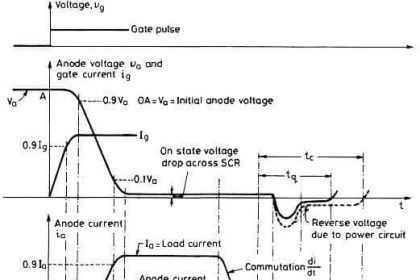
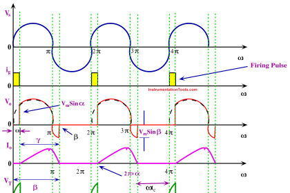
Thyristors T1 and T2 are forward biased during positive and negative half cycles respectively; these are therefore triggered accordingly. Suppose T2 is already conducting. After ωt = 0, van is positive, T1 is therefore forward biased, and when triggered at delay angle α, T1 gets turned on. At this firing angle a, supply voltage 2Vmsinα reverse biases T2„ this SCR is therefore turned off. Here T1 is called the incoming thyristor and T2 the outgoing thyristor.
As the incoming SCR is triggered, the AC supply voltage applies reverse bias across the outgoing thyristor and turns it off. Load current is also transferred from outgoing SCR to incoming SCR. This process of SCR being turned off by the natural reversal of AC supply voltage is called natural or line commutation. Thyristors T1 and T2 are triggered appropriately because they are forward-biased throughout the positive and negative half of the cycle, respectively.
Let’s assume T2 has already started. T1 is forward biased after ωt = 0, van is positive, and when triggered at delay angle α, T1 turns on. This SCR is shut off at this firing angle because supply voltage 2Vmsinα reverse biased T2. Here, T1 is referred to as the incoming thyristor, and T2 is the outgoing thyristor.
The AC supply voltage applies reverse bias across the outgoing thyristor and switches it off as the incoming SCR is triggered. Additionally, load current is transmitted from the leaving SCR to the receiving SCR.
Natural or line commutation is the term for the process whereby an SCR is turned off by a naturally occurring reversal in the AC supply voltage.
Van = Vmsinωt
Vbn = -Vnb = – Vmsinωt
Vab = Van+Vnb = 2Vmsinωt
By applying KVL to the above circuit (Equivalent circuit of mid-point converter)
VT2-Vbn+VT1 = 0
VT2 = Vbn-Van+VT1 = 0
Apply Van and Vbn in the above equation
VT2 = – Vmsinα – Vmsinα = -2Vmsinα
The above voltage is applied across the Thyristor T2 when T1 is conducting. Therefore, the T2 will be turned off. The same operation will take place during the next cycle
The circuit turn-off time of the midpoint converter is obtained by
tc = (????-α)/ω
The average voltage VO of the single-phase Midpoint Converter is computed as follows:
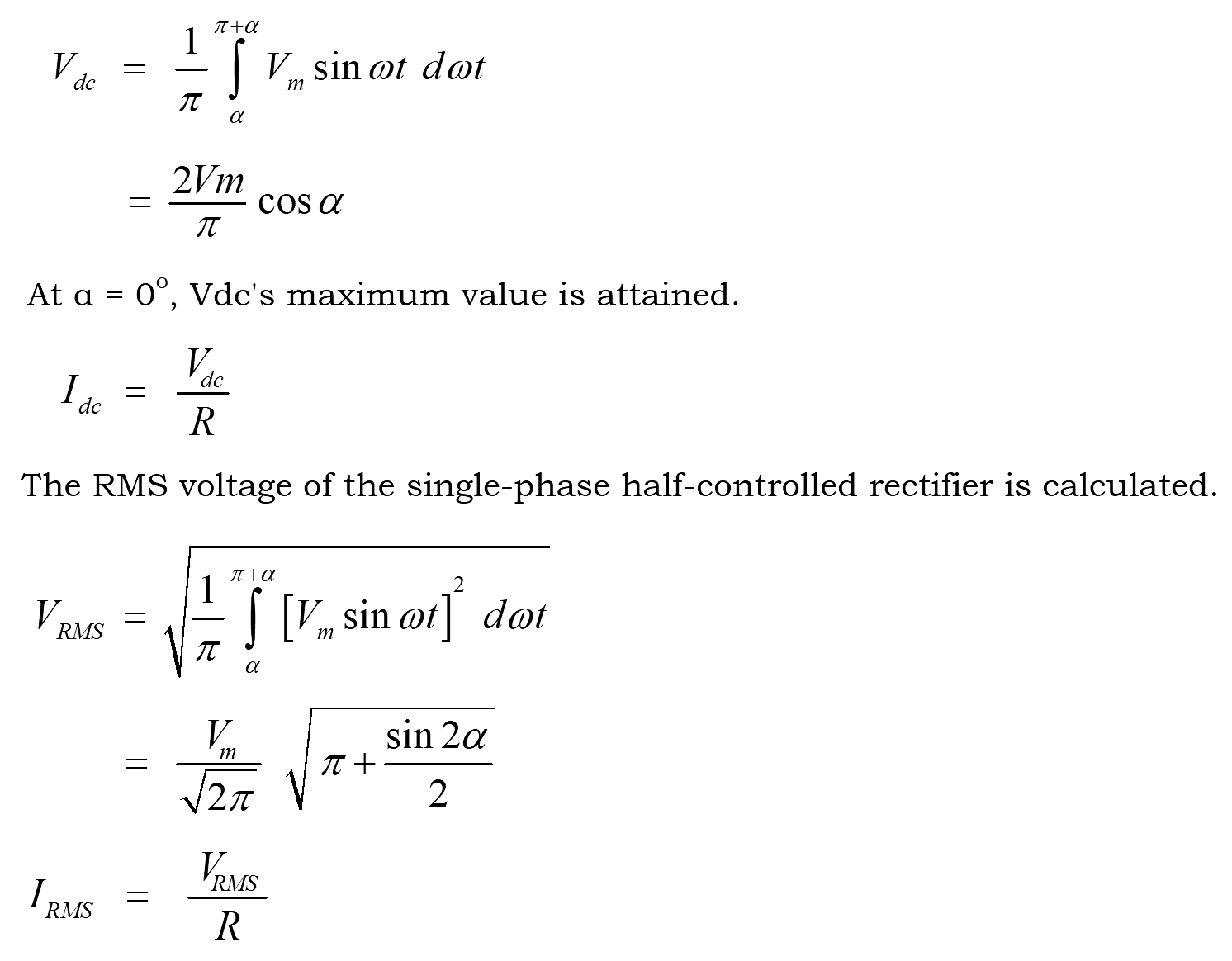
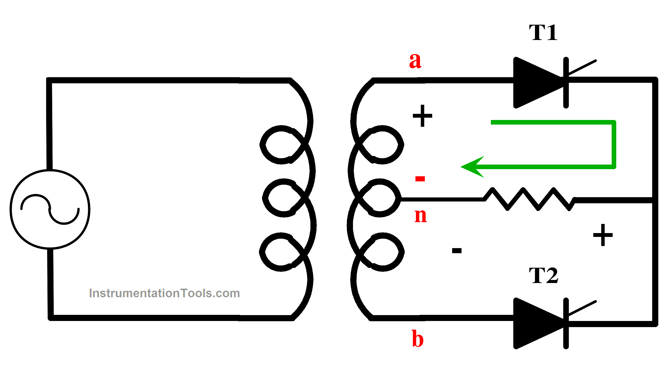
Fig. 2.a Full Converter During Positive Cycle
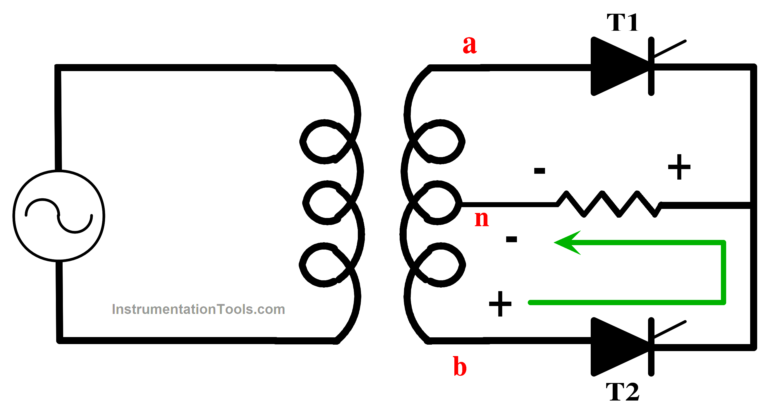
Fig. 2.b Full Converter During Negative Cycle
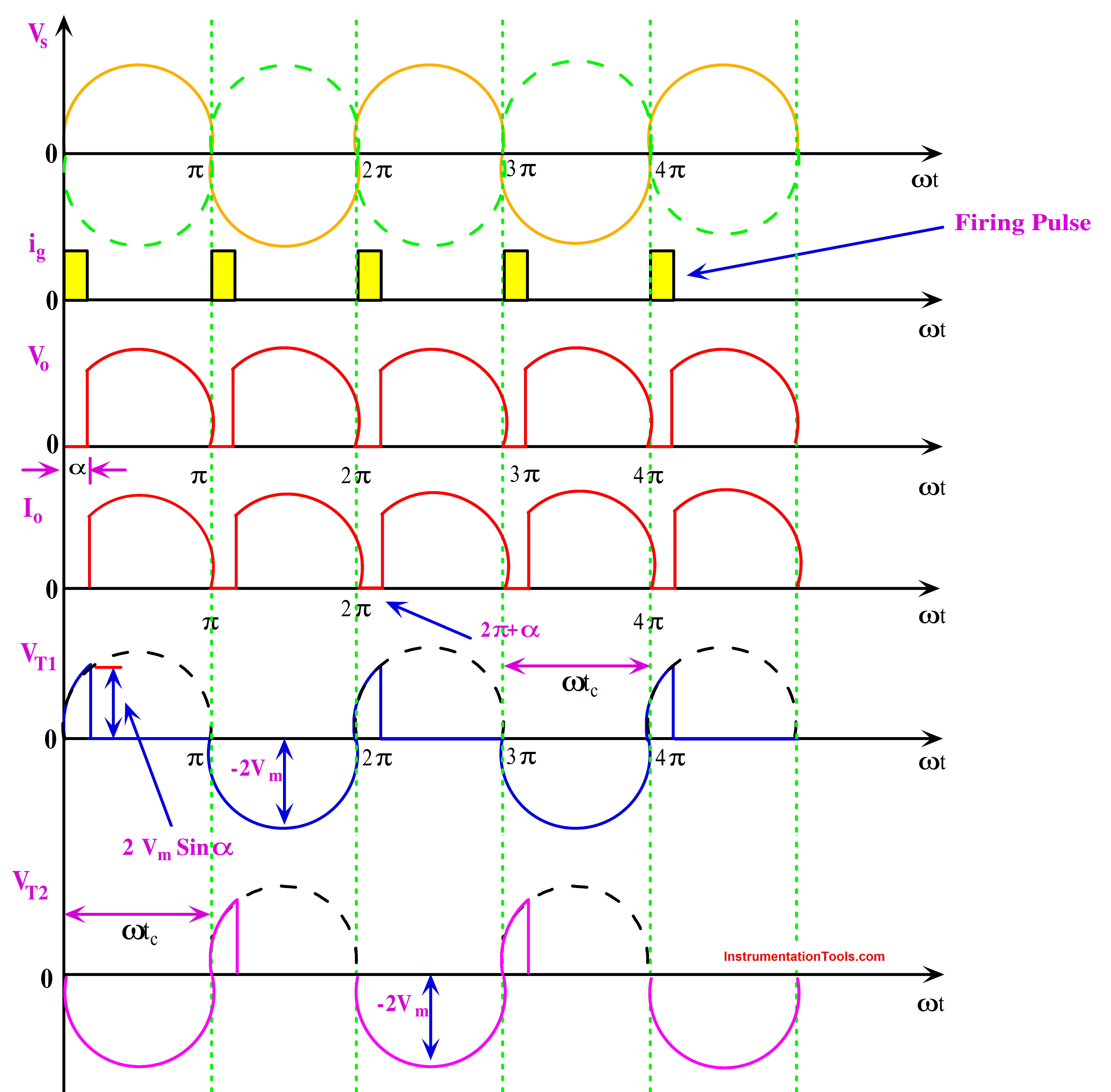
Fig. 3.a Mid Point Converter With R Load Output Waveform
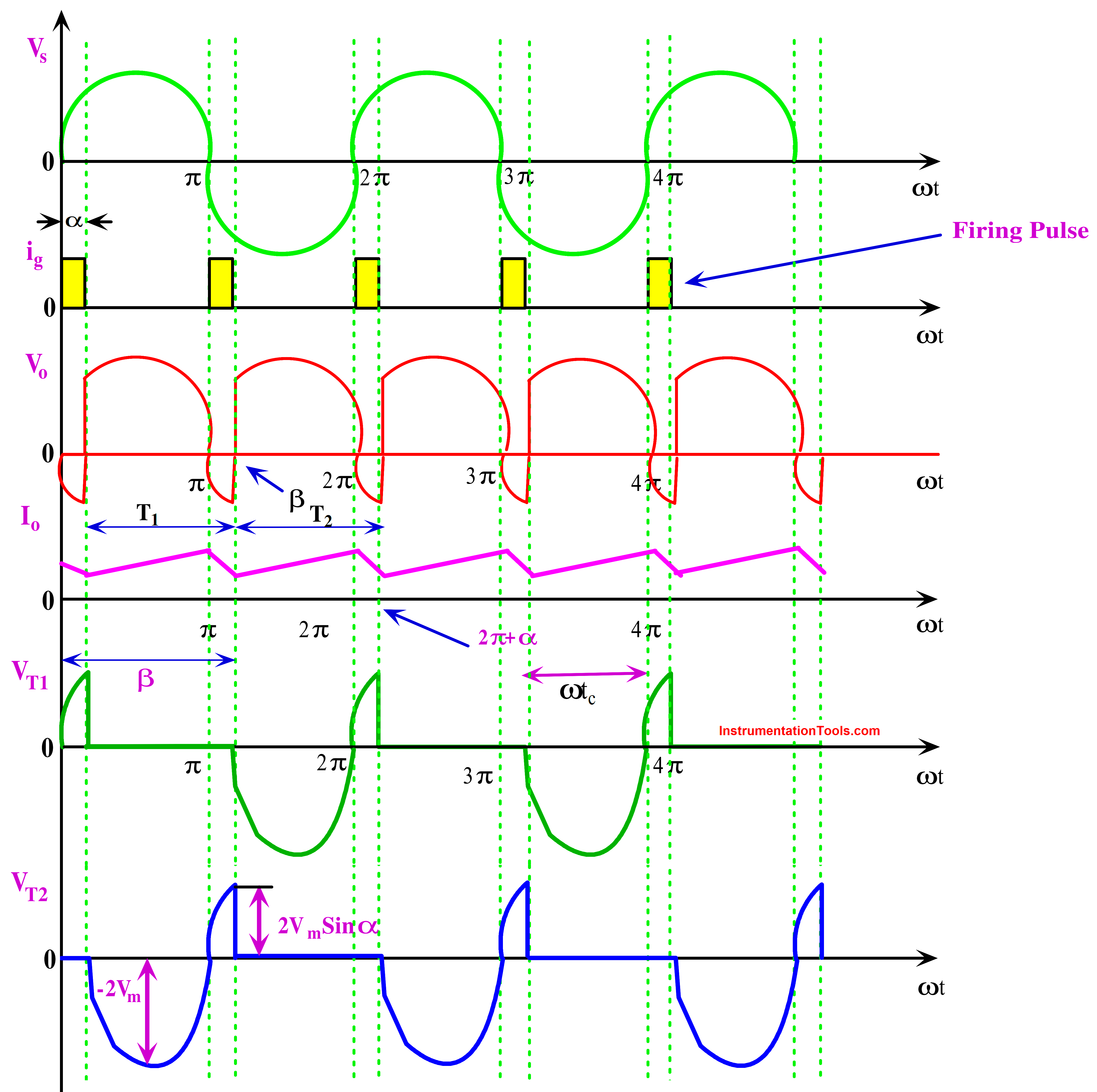
Fig. 3.b Mid Point Converter With RL Load Output Waveform
As stated in the specification sheet, the circuit turn-off time (tc) must be longer than the SCR turn-off time (tq). The entire secondary winding will be short-circuited if tc < tq, which results in commutation failure.
If the rate of rise of the fault current is rapid during commutation failure, the incoming SCR could be damaged if the protective parts do not remove the fault.
Comparison of Mid-point Converter and Full Converter
| S. No | Operation | Mid-Point Converter | Full Converter |
| 1 | Topology | Midpoint converters are a type of single-phase converter that uses a center-tapped transformer.The basic configuration includes two power switches (usually thyristors or IGBTs) and a center-tapped transformer. | Midpoint converters are a type of single-phase converter that uses a center-tapped transformer. The basic configuration includes two power switches (usually thyristors or IGBTs) and a center-tapped transformer. |
| 2 | Output | Full converters are typically used in high-power applications and use a transformer with multiple windings. The basic configuration includes four power switches (thyristors or IGBTs) that allow bidirectional power flow | Midpoint converters provide unidirectional output voltage. The output voltage waveform is pulsating DC, which can be filtered to obtain a relatively smooth DC voltage |
| 3 | Control | Control of full converters is more complex due to bidirectional power flow and the need for coordinated switching of the four switches. They offer better flexibility in controlling the output voltage and current waveform. | Full converters can provide both positive and negative output voltages. The output voltage can be controlled and regulated more effectively than midpoint converters. |
| 4 | Applications | Midpoint converters are commonly used in low-power motor drives, battery chargers, and small power supplies. | Full converters are used in high-power industrial applications, traction systems (like trains and trams), and HVDC (High Voltage Direct Current) transmission systems. |
Advantages of Mid-Point Converter
- The Mid-point converter utilizes two SCRs, current can flow in both directions, allowing for better control.
- The midpoint configuration allows for more efficient use of the transformer, reducing the harmonic content in the output current.
- By controlling the firing angles, the output voltage can be varied, allowing for controlled DC output.
Disadvantages of Mid-Point Converter
- The control circuitry to adjust the firing angles can be complex and may require precise timing.
- Despite being better than some other rectifier configurations, midpoint rectifiers can still introduce harmonics into the AC power system.
Matlab Results
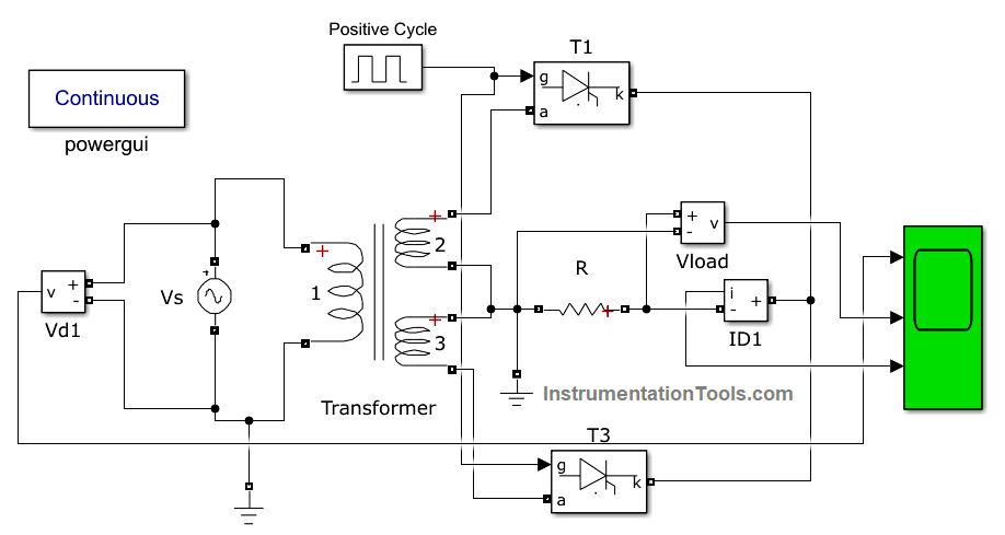
Fig.4. Simulink Circuit of Mid Point Converter With R Load
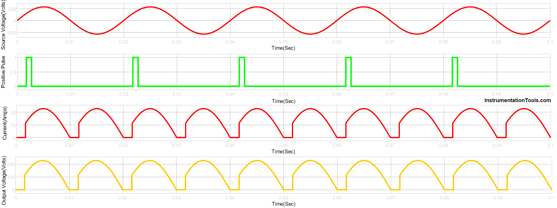
Fig.5 Simulink Response of Mid-point Converter With R Load
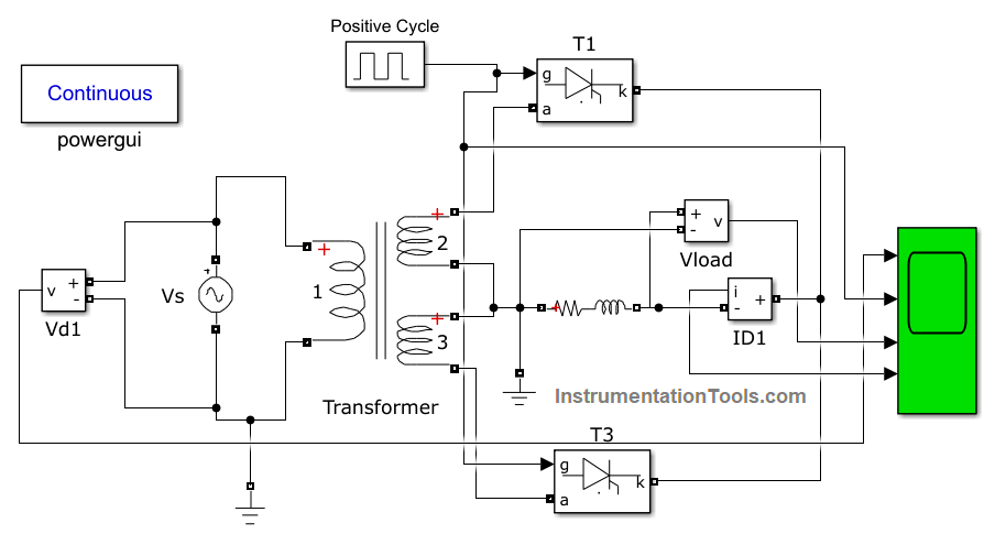
Fig.6. Simulink Circuit of Mid Point Converter With RL Load
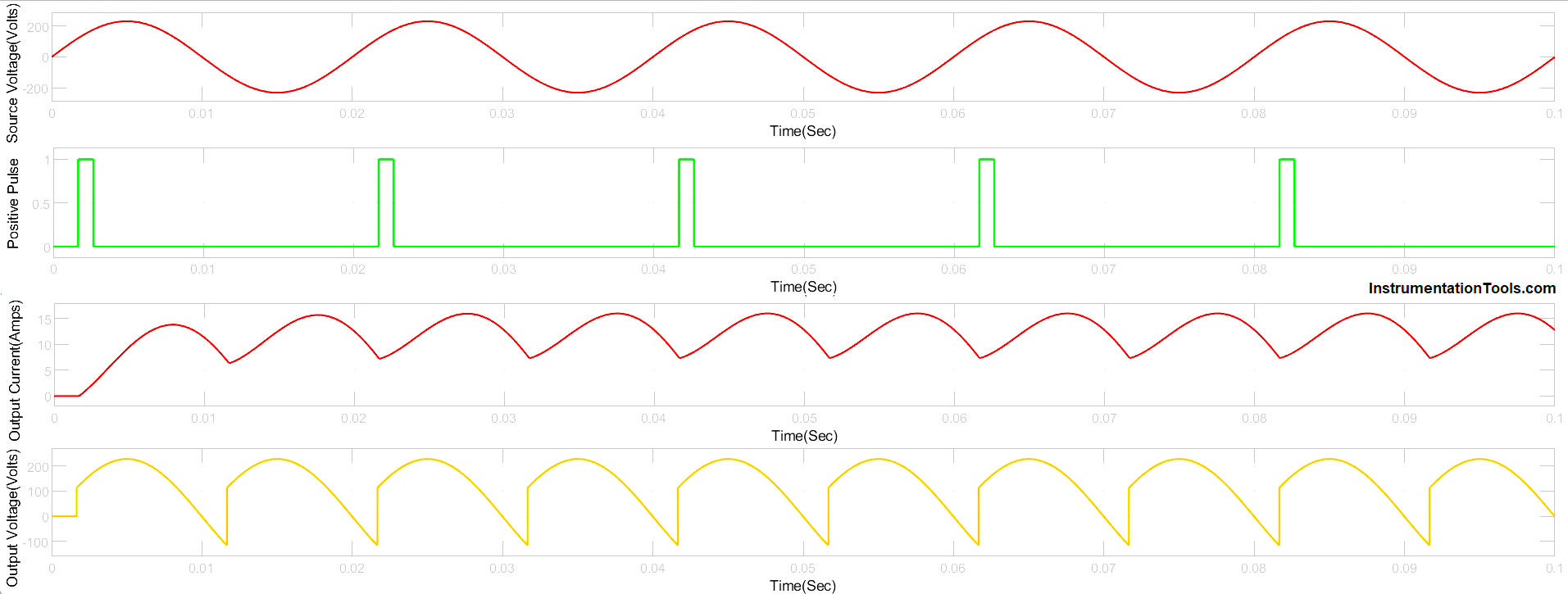
Fig.7 Simulink Response of Mid-point Converter With RL Load
The simulation output of the midpoint converter looks similar to the full converter only the changes in the circuit.
If you liked this article, then please subscribe to our YouTube Channel for Instrumentation, Electrical, PLC, and SCADA video tutorials.
You can also follow us on Facebook and Twitter to receive daily updates.
Read Next:
- Top 100 Power Electronics Projects
- Thyristor Triggering Circuits and Types
- Full-wave Rectifier With R and RL Load
- Phase Controlled Half Wave Rectifier RL Load
- Half-Wave Rectifier With Freewheeling Diode