This is a PLC Program for Positive edge pulse output for one scan cycle. Learn the ladder logic with the solution.
Positive Edge Pulse Output
Problem Description
In some applications, we need to run an operation/function based on external input signal. We can use a digital input as trigger command to activate that required function.
Sometimes we use positive transition of the digital input signal to trigger the command instead of continuous/full pulse digital input signal.
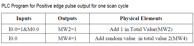
Here we consider an example of simple logic in which two registers values will be increment after receiving the trigger command. Each register have a preset value say value “1”. So on every trigger command, the adder register values will be increment by value “1”.
For adder 1 register we use positive edge (0 to 1) triggered input and for adder 2 register we use simple digital input (0 to 1 & 1 to 0) signal. We see the advantages and disadvantages of using triggering command with and without using positive edge.
We can use the same logic in other applications like Zeroing the register values, forcing the register values with defined value with little logic modification etc.
Problem

Solution
- We can solve these types of problem by positive edge or rising edge of the digital input.
- Here we will consider S7-300 PLC for programming, so we can monitor the value and simulate it. We can use PLC SIM for simulation purpose.
- Here we have considered one simple example. In this example we will consider “Adder 1” register which will add value “1” when transition occurs from 0 to 1 of the trigger command. The register value will be incremented by value 1 after each triggering.
- For “Adder 2” register, the value will be incremented after receiving the digital input. Here, we are not used the positive edge triggering.
List of Inputs/Outputs
Inputs List
- Trigger Command : I0.0
Memory Coil
- Positive Edge of trigger command : M0.0
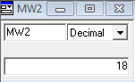
- Total Value : MW2
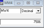
- Total Value 2 : MW4
PLC Ladder Logic
Network 1:
The initial value of “Adder 1″register is zero. After giving positive edge triggering command for 18 times, the output will be value 18 as it increments by value “1”.

Simulation (PLCSIM-300) for trigger command with positive edge.
Network 2:
The initial value of “Adder 2″register is zero. After giving triggering command (without positive/negative edge) for 18 times, the output will come some random number (say 7506) instead of value 18 as trigger command directly received.

Simulation (PLCSIM-300) for trigger command without positive edge.
PLC Logic Description
- In this application, we have used Siemens S7-300 PLC and TIA Portal Software for programming.
- Here we have considered two examples for positive edge explanation. Anyone can easily understand the concept.
- In Network 1, when trigger command (I0.0) is triggered then transition will occur from 0 to 1 and positive pulse instruction will be executed.
- Say “Adder 1″register will be stored with value “1” in MW0, if trigger command (I0.0) will be triggered then the value will be incremented by “1”.
- Here for example, we have triggered 18 times when adder 1 is zero, so adder added 18 in total Value (MW0)
- Another example we have taken in Network 2, without using positive pulse. so here you can see the result.
- Say, We have pressed or triggered 18 times but it added 7506 (this is random value it can be different during simulation) in total Value 2 (MW4) so it is not proper addition. Because one pulse have rising or falling edges / positive or negative pulses (o to 1 and 1 to 0).
- Here also we have used PLC SIM for simulation, so we can simulate the total addition. In first network we have added positive edge so simulator is showing 18. In second network we have added trigger command without positive edge so it is showing some random value.
- This is the concept of positive edge, we can use this positive edge during any programming application.
- Above program and simulation is only for explanation purpose and simulation value can be different at simulation time.
Result
Note: The above PLC Logic provided for basic idea about application of Positive edge trigger command in PLC Logic. The Logic is limited and not complete application.
Author: Bhavesh
If you liked this article, then please subscribe to our YouTube Channel for PLC and SCADA video tutorials.
You can also follow us on Facebook and Twitter to receive daily updates.
Read Next:
- PLC Program for Mixing Tank
- Siemens PLC Interview Questions
- PLC Heat and Bend Glass Tubes
- Siemens PLC Comparator Logic
- SLC 500 PLC Programming