Inst ToolsInst ToolsInst Tools
  • Courses
  • Automation
    • PLC
    • Control System
    • Safety System
    • Communication
    • Fire & Gas System
  • Instrumentation
    • Design
    • Pressure
    • Temperature
    • Flow
    • Level
    • Vibration
    • Analyzer
    • Control Valve
    • Switch
    • Calibration
    • Erection & Commissioning
  • Interview
    • Instrumentation
    • Electrical
    • Electronics
    • Practical
  • Q&A
    • Instrumentation
    • Control System
    • Electrical
    • Electronics
    • Analog Electronics
    • Digital Electronics
    • Power Electronics
    • Microprocessor
  • Request
Search
  • Books
  • Software
  • Projects
  • Process
  • Tools
  • Basics
  • Formula
  • Power Plant
  • Root Cause Analysis
  • Electrical Basics
  • Animation
  • Standards
  • 4-20 mA Course
  • Siemens PLC Course
Reading: 3 Phase Motor Control using PLC Ladder Logic
Share
Font ResizerAa
Inst ToolsInst Tools
Font ResizerAa
  • Courses
  • Design
  • PLC
  • Interview
  • Control System
Search
  • Courses
  • Automation
    • PLC
    • Control System
    • Safety System
    • Communication
    • Fire & Gas System
  • Instrumentation
    • Design
    • Pressure
    • Temperature
    • Flow
    • Level
    • Vibration
    • Analyzer
    • Control Valve
    • Switch
    • Calibration
    • Erection & Commissioning
  • Interview
    • Instrumentation
    • Electrical
    • Electronics
    • Practical
  • Q&A
    • Instrumentation
    • Control System
    • Electrical
    • Electronics
    • Analog Electronics
    • Digital Electronics
    • Power Electronics
    • Microprocessor
  • Request
Follow US
All rights reserved. Reproduction in whole or in part without written permission is prohibited.
Inst Tools > Blog > Guest Articles > 3 Phase Motor Control using PLC Ladder Logic

3 Phase Motor Control using PLC Ladder Logic

Create a 3 Phase Motor Control using PLC Ladder Logic. Read PLC programming books pdf free download and PLC programs beginner guide.

Last updated: November 3, 2023 9:53 am
Editorial Staff
Guest Articles PLC Tutorials
1 Comment
Share
5 Min Read
SHARE

This is a PLC Program for Forward and Reverse control for 3 Phase Asynchronous Motor.

Contents
3 Phase Motor Control using PLCProblem DiagramProblem SolutionPLC Inputs ListPLC Outputs ListPLC Ladder diagram for Forward/Reverse control of MotorLadder Logic DescriptionRuntime Test Cases

3 Phase Motor Control using PLC

Problem Description

There are lots of motors and conveyors used in industries for different purposes.

In some cases, motors or conveyors need forward and reverse operation for some control purpose.

For example overhead crane, in crane every time operators moves it forward and reverse for material handling.

So we can use PLC systems for programming the motor for forward/reverse operation.
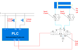
Problem Diagram

PLC Program for Forward and Reverse Motor control

Problem Solution

In this case, we need to operate motor in both direction, that can be possible only by forward/Reverse Control Relay Circuit or through Logic.

Here we solve this problem by using simple Forward/Reverse Control Logic in the PLC.

So here we will consider one 3 phase motor for Forward and Reverse Operation.

And we will take two contactors or relays for motor control because we need two different directions here i.e. Forward/Reverse. First contactor for Forward Direction control and Second contactor for Reverse Direction control of Motor.

Also we should consider three push buttons i.e. for forward, reverse and stop functions of motor.

So here operator will use FWD PB for forward operation, REV PB for reverse operation and STOP PB for stop function.

PLC Inputs List

  • FWD PB : I0.0
  • REV : I0.1
  • STOP PB : I0.2
  • Motor Trip : I0.3

PLC Outputs List

  • Motor forward : Q0.0
  • Motor reverse : Q0.1

PLC Ladder diagram for Forward/Reverse control of Motor

Three Phase Motor PLC Ladder Logic

Ladder Logic Description

  • In this application, we will use Siemens S7-1200 PLC and TIA Portal Software for programming. We can also design this logic with relay circuit.
  • This circuit is also known as Forward/Reverse control for 3 Phase Induction Motor.
  • We will write logic for forward condition in Network 1. Here we use the NO contact of FWD PB (I0.0) for forward operation of the motor, we are using push button so we need to use one NO contact of motor forward output coil (Q0.0) for latching purpose. (Push button only provides momentary contact and we need to latch the action so motor forward coil contact will be used)
  • Put NC contact of motor reverse output (Q0.1) in series for unlatching the circuit because both forward and reverse should not run at the same time.
  • Now write the logic for reverse condition in network 2. Here we will take NO contact of REV PB (I0.2) for motor reverse function and also take one more NO contact of the motor reverse output coil(Q0.1) for latching the motor reverse output (QO.1). (Push button only provides momentary contact and we need to latch the action so motor forward coil contact will be used)
  • Here also put NC contact of motor forward output coil (Q0.0) in series for unlatching the circuit because both forward and reverse should not run at the same time.
  • For interlocking purpose put NC contact of FWD PB (I0.0) in series with REV PB (I0.2) and put NC contact of REV PB (I0.2) in series with FWD PB (I0.0).
  • Put NC Contact in series in both network so operator can stop forward or reverse rotation by pressing STOP PB
  • Here we have used OLR for Protection of motor so add NC contact of Motor trip (I0.3) in series in both the network for motor protection

Runtime Test Cases

PLC Ladder Logic for Motor Control

Note: The above PLC Logic provided for basic idea about application of PLC Logic for 3 Phase Asynchronous Motor Control. The Logic is limited and not complete application.

Author: Bhavesh

If you liked this article, then please subscribe to our YouTube Channel for PLC and SCADA video tutorials.

You can also follow us on Facebook and Twitter to receive daily updates.

Read Next:

  • PLC Automatic Liquid Mixing
  • Sequential Motor Control PLC
  • PLC Conditional Control Logic
  • Continuous Filling Operation in PLC
  • Automatic Empty Bottle detection
Don't Miss Our Updates
Be the first to get exclusive content straight to your email.
We promise not to spam you. You can unsubscribe at any time.
Invalid email address
You've successfully subscribed !

Continue Reading

Programmable Logic Controller Practice Tests
Your First Steps Through STL Language
Micro Memory Card (MMC) in Siemens PLC
SCADA Interview Questions and Answers
Why Use a Current Loop?
100 PLC Quiz Questions : True or False
Share This Article
Facebook Whatsapp Whatsapp LinkedIn Copy Link
Share
1 Comment
  • DEVI says:
    April 8, 2023 at 4:57 am

    Thank you

    Reply

Leave a Reply Cancel reply

Your email address will not be published. Required fields are marked *

Stay Connected

128.3kFollowersLike
69.1kFollowersFollow
210kSubscribersSubscribe
38kFollowersFollow

Categories

Explore More

Siemens S7 300 CPU Status and LED Errors Explanation
PLC Program for 2 Push buttons to Control 1 Output
PLC Power Supply and Operating Voltages
Conveyor Operation with a Backup Motor using PLC Ladder Diagram
XG5000 Example of Simple Conveyor Control PLC Program
Water Fountain Control Logic – PLC Exercises and Solutions
Siemens LOGO PLC Complete Programming Course
Difference Between PLC and SCADA

Keep Learning

LCS Configuration equipped with LOTO Facility

Motor Control Signal Interface

Namur Digital Input Card

What is Namur Digital Input Card?

Omron PLC Mixing System

Mixing Program with Timers and Counters in Omron PLC

UDT in the PLC Programming

Implement UDT in PLC Programming: User-Defined Data Type

Midline output instruction

What is Midline Instruction in Siemens PLC?

Ladder Diagram circuit

PLC Practice Questions

Motor Feedback Fail Logic in PLC

Motor Feedback Fail Logic in PLC

Types of Limit Switches

Types of Limit Switches – Principle, Advantages, Disadvantages

Learn More

Best YouTube Channels for Cyber Security

Best YouTube Channels to Learn Cyber Security

VLSI Projects for Engineering Students

700+ VLSI Projects for Engineering Students

PLC Timer Application in Security Camera Recording

PLC Timer Application in Security Camera Recording

Radar Level Transmitter in Briddle level Measurement

Radar Level Transmitter in Briddle level Measurement

Power Electronics Objective Questions

Full Wave Rectifiers Objective Questions and Answers

Instrument Calibration Lab Exercise

Instrument Calibration Lab Exercise

Zener Diode Voltage Regulator Operation

Zener Diode Voltage Regulator Operation

Root Locus Concepts Objective Questions

Construction of Root Loci

Menu

  • About
  • Privacy Policy
  • Copyright

Quick Links

  • Learn PLC
  • Helping Hand
  • Part Time Job

YouTube Subscribe

Follow US
All rights reserved. Reproduction in whole or in part without written permission is prohibited.
Welcome Back!

Sign in to your account

Username or Email Address
Password

Lost your password?