This is the PLC Program for Sequential Motor Operating System.
Sequential Motor Control
Problem Description
In many industries, there are lots of motors are used. Sometimes we need to start more than one motor in an application.
When we have a low incoming power supply rating, then there is a chance the incoming MCB will trip when one or more motors will START in parallel because they will consume more power.
Here we will consider one similar example where we START each motor one by one.
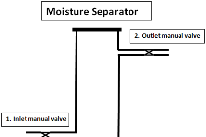
Problem Diagram

Problem Solution
The problem can be solved by using PLC programming or relay logic.
In this case, we have to operate motors sequentially. There are total 3 motors to be controlled in a sequence. so that each motor will start sequentially, say Motor 1 will START then after some delay then motor 2 will start and after some delay motor 3 will start.
So that whole operation will take 10 seconds to start all motors in a sequence. By providing this delay we can avoid the problem of taking large
current by motors during initial stat up.
All motors will be operate in the sequence and 5 seconds time delay is to be provided between operations of each motor.
Here will write logic for sequential operation for motors using PLC.
List of Inputs & Output
Inputs List
- Start PB : I0.0
- Stop PB: I0.1
Outputs List
- Cycle on : Q0.0
- Motor 1: Q0.1
- Motor 2 : Q0.2
- Motor 3 : Q0.3
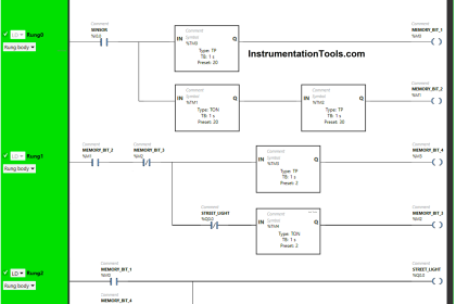
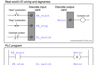
PLC Ladder Diagram for Sequential Motor Control

Ladder Logic Explained
In this application, we used Siemens S7-1200 PLC and TIA Portal Software for programming. We can also design this logic with relay circuit.
Network 1:
In Network 1, we wrote logic for cycle ON condition. Here cycle ON (Q0.0) lamp will indicate cycle status. Cycle can be started by pressing START PB (I0.0) push button and can be Stopped by pressing STOP PB (I0.1) push button.
When cycle will be ON, at same time Motor 1(Q0.1) will be Started. And at the same time, timer instruction will be executed.
Network 2:
In Network 2, the NO contact of Motor 1 starts Timer T1 and when Timer for Motor 2 (Q0.1) will reach the set value 5 seconds. Then NO contact of the T1 will START the Motor 2 (Q0.1).
Network 3:
In Network 3. we have taken logic for motor 3. Here we have given NO contact of motor 2 for starting the timer of motor 3. When T2 will reach the set value 5s , the NO contact of the T2 will START the Motor 3(Q0.0).
When STOP PB (I0.1) will be pressed then NC contact will be activated which makes Cycle (Q0.0) OFF. And also motor 2 and 3 will stop working.
Runtime Test Cases
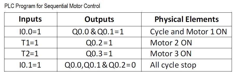
Note: The above PLC Logic provided for basic idea about application of PLC in Sequential Motor Control. The Logic is limited and not complete application.
Author: Bhavesh
If you liked this article, then please subscribe to our YouTube Channel for PLC and SCADA video tutorials.
You can also follow us on Facebook and Twitter to receive daily updates.
Read Next:


thank for INST TOOL program