Inst ToolsInst ToolsInst Tools
  • Courses
  • Videos
  • Q & A
    • Interview
      • Instrumentation
      • Electronics
      • Electrical
      • Practical Questions
    • MCQ
      • Instrumentation MCQ
      • Electrical MCQ
      • Electronics MCQ
      • Control Systems MCQ
      • Analog Electronics MCQ
      • Digital Electronics MCQ
      • Power Electronics MCQ
      • Microprocessor MCQ
      • Multiple Choice Questions
  • EE
    • Electronics
      • Electronics Q & A
      • Electronic Basics
      • Electronic Devices & Circuits
      • Electronics Animation
      • Digital Electronics
    • Electrical
      • Electrical Basics
      • Electrical Q & A
      • Power Electronics
      • Electrical Machines
      • Electrical Animation
      • Power Systems
      • Switchgear & Protection
      • Transmission & Distribution
  • Measure
    • Control Valves
    • Calibration
    • Temperature
    • Pressure
    • Flow
    • Level
    • Analyzers
    • Switches
    • Vibration
    • Solenoid Valve
  • Control
    • PLC Tutorials
    • Control Systems
    • Safety Instrumented System (SIS)
    • Communication
    • Fire & Gas System
  • More
    • Design
    • Tools
    • Animation
    • Basics
    • Formulas
    • Standards
    • TextBooks
    • Common
    • Software
    • Excel Tools
    • Erection & Commissioning
    • Process Fundamentals
    • Videos
    • Books
Search
All rights reserved. Reproduction in whole or in part without written permission is prohibited.
Reading: PLC Program for Continuous Filling Operation
Share
Notification Show More
Font ResizerAa
Inst ToolsInst Tools
Font ResizerAa
  • Courses
  • PLC Tutorials
  • Control Systems
Search
  • Courses
  • Videos
  • Q & A
    • Interview
    • MCQ
  • EE
    • Electronics
    • Electrical
  • Measure
    • Control Valves
    • Calibration
    • Temperature
    • Pressure
    • Flow
    • Level
    • Analyzers
    • Switches
    • Vibration
    • Solenoid Valve
  • Control
    • PLC Tutorials
    • Control Systems
    • Safety Instrumented System (SIS)
    • Communication
    • Fire & Gas System
  • More
    • Design
    • Tools
    • Animation
    • Basics
    • Formulas
    • Standards
    • TextBooks
    • Common
    • Software
    • Excel Tools
    • Erection & Commissioning
    • Process Fundamentals
    • Videos
    • Books
Follow US
All rights reserved. Reproduction in whole or in part without written permission is prohibited.
Inst Tools > Blog > PLC Tutorials > PLC Program for Continuous Filling Operation

PLC Program for Continuous Filling Operation

PLC Program: A Continuous Filling Operation requires boxes moving on a conveyor to be automatically positioned and filled.

Last updated: November 2, 2023 5:00 pm
Editorial Staff
PLC Tutorials
3 Comments
Share
6 Min Read
SHARE

PLC Program : A Continuous Filling Operation requires boxes moving on a conveyor to be automatically positioned and filled.

Contents
PLC Program for Continuous Filling OperationPurposePLC LogicExplanation

PLC Program for Continuous Filling Operation

PLC Program for Filling Operation

Purpose

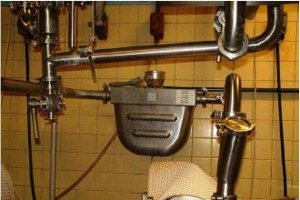
Solenoid : To control the product filling from the hooper. Solenoid will be activated after the box positioned (proximity switch activation) and again de-activates after the level switch activated (level full).

Level Switch : To detect the product level in the filling box.

Proximity Switch : To position the box exactly below the hooper.

Motor : To run the conveyor such that the box will move accordingly.

Local Control Panel : it has START & STOP buttons used to control the sequence.

Indication Panel : It displays the plant/batch status. Status signals are Run/Stand By/Full.
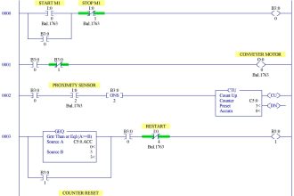
PLC Logic

PLC Bottle Filling Ladder Logic

The below are the default positions :

  • STOP Switch : Normally Close (NC)
  • START Switch : Normally Open (NO)
  • Proximity Switch : Normally Open (NO)
  • Level Switch : Normally Open (NO)

Note : In ladder logic we can use either NO or NC contacts as default of proximity & level switch as required. if we use NO then it becomes NC after switch activated. if we use NC then it becomes NO after switch activated.

Explanation

Here we have 5 rungs / complete lines in the above ladder logic.

First Rung:

It has STOP, START & RUN Indication. STOP default NC, START is NO, when we press START command then both STOP & START are NC so the output RUN will be activated.

RUN Indication will be displayed in indication panel. As START is a push button which generates a momentary command only.

So we use a logical NO contact from RUN output. when RUN is activated, the NO becomes NC and Holds/latches the START command and RUN will be continuously activated even though START signal is lost as it is momentary type.

Second Rung:

it is used to indicate STAND BY signal status in the indicator panel. RUN indication NC contact is connected to STANDBY.

so when RUN signal activated or process started then NC becomes NO and STAND BY indication will be disabled. if it is not running then stand by will be activated.

Third Rung:

it is used to indicate FULL signal status in the indicator panel. when level switch & proximity switch are activated then NO contacts will become NC and FULL signal status will be enabled.

Fourth Rung:

It is used to control the Motor either START/STOP. Proximity switch NC contact is used & RUN signal NO contact is used here to control the Motor.

so when we press START button, the RUN will be activated ( as discussed in First Rung ) so RUN signal NO contact will becomes NC.

Both proximity & RUN signals are enabled/healthy then Motor will be started and conveyor will start running and box/package will start move.

once the box reached before Hooper then proximity switch will be activated. So proximity switch NC contact becomes NO, so Motor will be stopped immediately.

After filling, the box has to move again and to reach other side. so here we use level switch NO contact across proximity switch.

When Filling completed, Level switch contact changes from NO to NC, so again the motor starts and moves the box to other end.

Fifth Rung:

It is used to control the solenoid valve operation. If solenoid activated then it starts filling the box and if solenoid valve de-activates then the filling will be stopped.

Here we mainly use RUN signal NO contact, Level Switch NC contact, Proximity NO contact to control the solenoid valve.

Solenoid valve will be activated when START command is given ( RUN signal NO contact becomes NC), when level is Zero (Level switch NC contact used as default here ), when Box is placed under the hooper ( proximity switch NO contact used.

so when box arrives under hooper, NO contact becomes NC ) , after all the logics are healthy then solenoid valve will be activated and starts filling.

if level reaches 100% then level switch will become NO and thus stopping the filling by de-activating the solenoid valve.  We used proximity switch here because the filling has to be started when the box placed in correct position.

After filling the box move out and filling again will start when next box comes under Hooper.

If you liked this article, then please subscribe to our YouTube Channel for PLC and SCADA video tutorials.

You can also follow us on Facebook and Twitter to receive daily updates.

Read Next:

  • PLC Program for Conveyor Motor
  • 3 Phase Motor Control using PLC
  • PLC Tank Heating Control
  • Basics of Limit switches
  • Switch Types
Don't Miss Our Updates
Be the first to get exclusive content straight to your email.
We promise not to spam you. You can unsubscribe at any time.
Invalid email address
You've successfully subscribed !

Continue Reading

Configuring and Usage of Cyclic Interrupts TIA Portal (OB 30+)
Sink or Source? Normally Open or Normally Closed?
Relay circuits
PLC Light Sequence Control using Bit Shift Registers
How to do Scaling for Analog Input in RSLogix 500?
Difference Between Microcontroller and PLC
Share This Article
Facebook Whatsapp Whatsapp LinkedIn Copy Link
Share
3 Comments
  • Khalid Hussein says:
    July 17, 2021 at 11:50 pm

    Wrong ladder logic.
    —-I/I—-I/I—–( )-
    Prox.s

    Reply
  • helal basho says:
    November 23, 2021 at 6:36 pm

    – How can ” when Box is placed under the hooper ” ???
    – Is this system is fully automatic after turning it on from local control panel ???

    Reply
  • Simiey says:
    October 4, 2022 at 1:14 am

    I believe that there is more than one way to solve this.

    Reply

Leave a Reply Cancel reply

Your email address will not be published. Required fields are marked *

Stay Connected

128.3kFollowersLike
69.1kFollowersFollow
208kSubscribersSubscribe
38kFollowersFollow

Categories

Explore More

Single-acting Cylinder OR Logic Operation (PLC and Sensors)
Types of Interrupt OB in Siemens Tia Portal
Automatic Car Washing using PLC
Network Switch Port Allocation Details
What is a Annunciator Panel?
Introduction to PLC Ladder Diagrams
Real-Time Clock in Omron PLC? – CX Programmer
PLC Logic Example on Multiple Switches and Motors

Keep Learning

Example Program Logic in Allen Bradley PLC

PLC Programming Examples on Industrial Automation

PLC Batch System for 4 Tanks Mixing using CX-Programmer

PLC Batch System for 4 Tanks Mixing using CX-Programmer

How to export in Vijeo Designer

Vijeo Designer software – Import and Export

DCS Marshalling Cabinet Checks

PLC, DCS, and ESD Marshalling Cabinet Checks

DCS Vs PLC

DCS versus PLC Architecture

Free Download SCADA Softwares

Free SCADA Software Download

Configuration of Siemens VFD Using TIA Portal

Configuration of Siemens VFD Using TIA Portal Start drive

Free Allen Bradley PLC Training Course

Free Allen Bradley PLC Ladder Logic Training Course

Learn More

Industrial Automation Components

Industrial Automation Components Questions and Answers

Power Electronics Objective Questions

PWM Inverter Quiz

Upgrading and Migration of PLC Systems

Upgrading and Migration of PLC Systems

Functional Design Specifications (FDS) for DCS and SIS Projects

Functional Design Specifications for DCS and SIS Projects – FDS Document

Sensors and Transducers Test

Sensors and Transducers Test

Calibration Procedure of displacer type Level transmitter

Calibration of Displacer Level Transmitter

Problem with Pirani Gauge

Problem with Pirani Gauge

Diaphragm Pump

What is a Diaphragm Pump?

Follow US
All rights reserved. Reproduction in whole or in part without written permission is prohibited.
Welcome Back!

Sign in to your account

Username or Email Address
Password

Lost your password?