Inst ToolsInst ToolsInst Tools
  • Courses
  • Automation
    • PLC
    • Control System
    • Safety System
    • Communication
    • Fire & Gas System
  • Instrumentation
    • Design
    • Pressure
    • Temperature
    • Flow
    • Level
    • Vibration
    • Analyzer
    • Control Valve
    • Switch
    • Calibration
    • Erection & Commissioning
  • Interview
    • Instrumentation
    • Electrical
    • Electronics
    • Practical
  • Q&A
    • Instrumentation
    • Control System
    • Electrical
    • Electronics
    • Analog Electronics
    • Digital Electronics
    • Power Electronics
    • Microprocessor
  • Request
Search
  • Books
  • Software
  • Projects
  • Process
  • Tools
  • Basics
  • Formula
  • Power Plant
  • Root Cause Analysis
  • Electrical Basics
  • Animation
  • Standards
  • 4-20 mA Course
  • Siemens PLC Course
Reading: Classroom Bell System – PLC Programming Practice Examples
Share
Notification Show More
Font ResizerAa
Inst ToolsInst Tools
Font ResizerAa
  • Courses
  • Design
  • PLC
  • Interview
  • Control System
Search
  • Courses
  • Automation
    • PLC
    • Control System
    • Safety System
    • Communication
    • Fire & Gas System
  • Instrumentation
    • Design
    • Pressure
    • Temperature
    • Flow
    • Level
    • Vibration
    • Analyzer
    • Control Valve
    • Switch
    • Calibration
    • Erection & Commissioning
  • Interview
    • Instrumentation
    • Electrical
    • Electronics
    • Practical
  • Q&A
    • Instrumentation
    • Control System
    • Electrical
    • Electronics
    • Analog Electronics
    • Digital Electronics
    • Power Electronics
    • Microprocessor
  • Request
Follow US
All rights reserved. Reproduction in whole or in part without written permission is prohibited.
Inst Tools > Blog > PLC Tutorials > Classroom Bell System – PLC Programming Practice Examples

Classroom Bell System – PLC Programming Practice Examples

Now we discuss the classroom bell system logic to learn the PLC programming with practice examples and solutions.

Last updated: April 28, 2024 7:25 pm
Editorial Staff
PLC Tutorials
No Comments
Share
6 Min Read
SHARE

Now we discuss the classroom bell system logic to learn the PLC programming with practice examples and solutions.

Contents
Classroom Bell SystemPLC Technical Training VideosInputs & OutputsPLC Programming Practice ExamplesProgram DescriptionPLC Program TestingWhen the Start Button is turned ONWhen the Add button is turned ON

Note: These PLC programs are primarily for engineering students to learn and practice the problems.

Classroom Bell System

Problem Statement:

Design a PLC ladder logic for the following application.

We are using two toggle switches to control Bell.

The bell should ring for 10 seconds after every 45 minutes (Let’s take it as 1 minute). If the add button is pressed then there will be a time delay of 15 seconds for the bell to get ON.

PLC Technical Training Videos

The best PLC technical training videos are available on the Instrumentation Tools YouTube channel for free of cost.

The below video explains the given problem statement and its solution.

PLC Programming Practice Examples - Classroom Bell System

Inputs & Outputs

Digital Inputs:

Start Button: I0.0

Add Button: I0.1

Digital Outputs:

Bell: Q0.0

PLC Programming Practice Examples
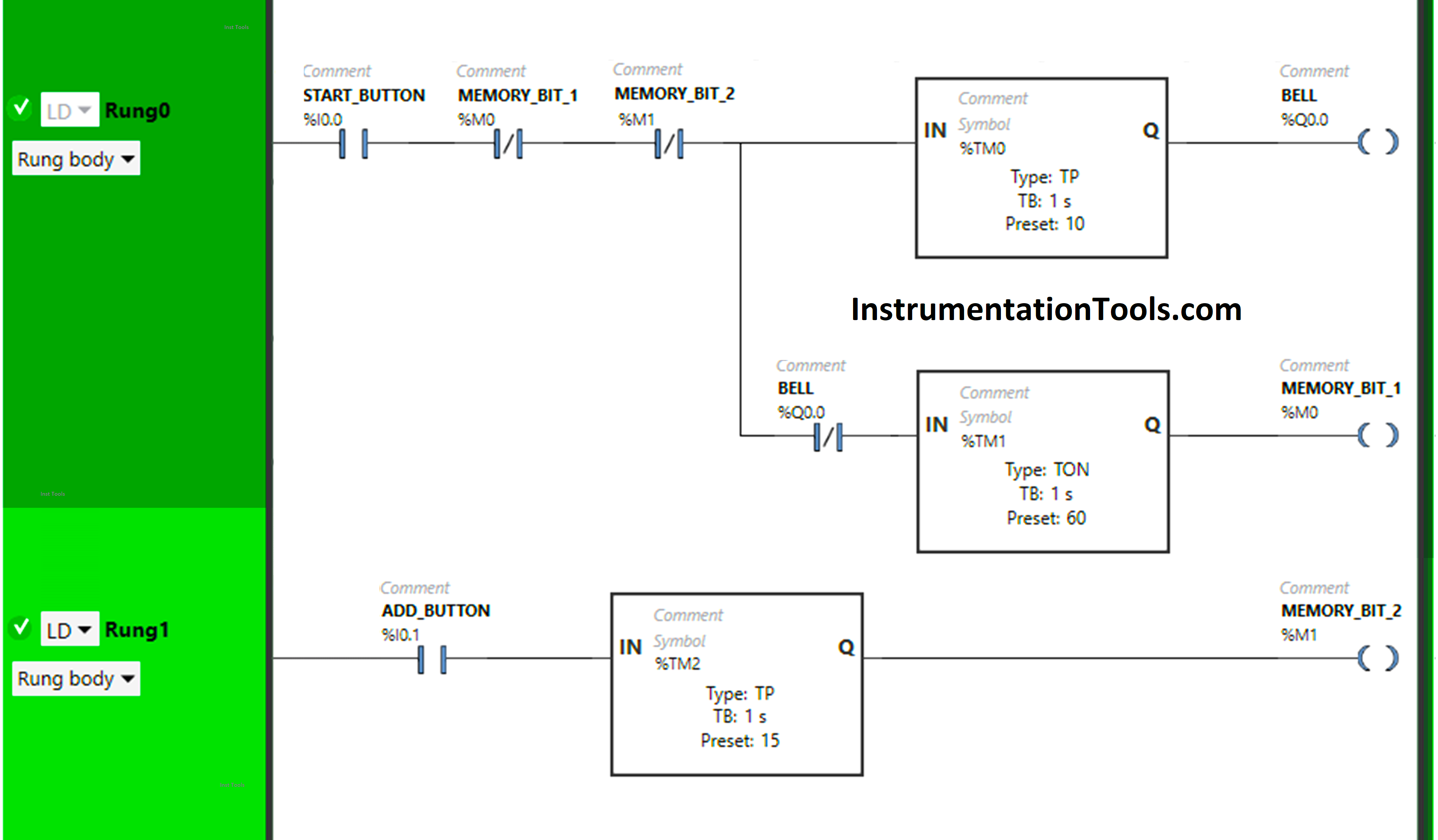
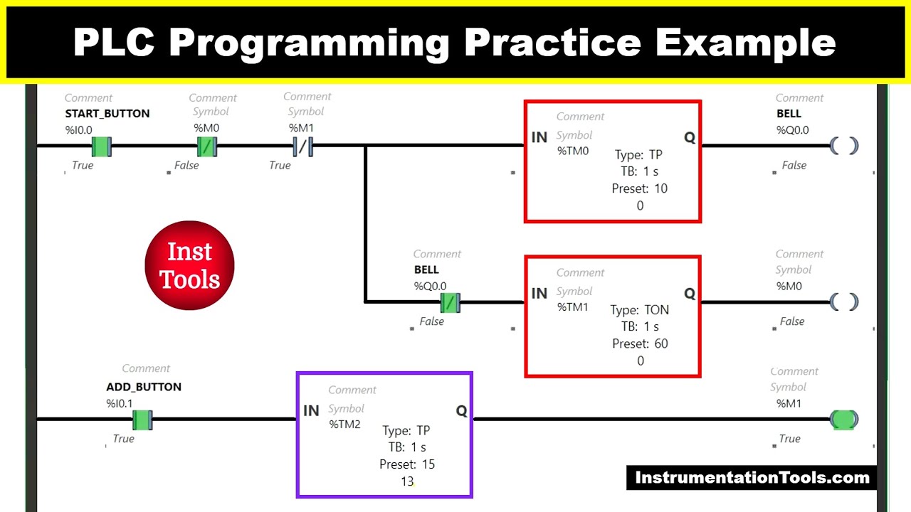
PLC Programming Classroom Bell System

Program Description

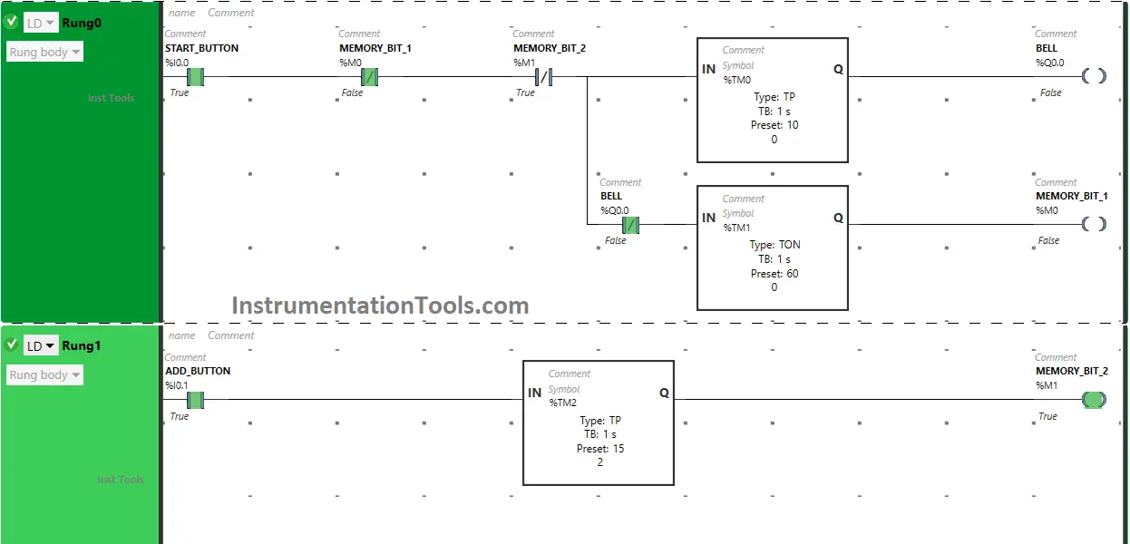
We have used Normally Open Contacts for the Start Button (I0.0) and Add Button (I0.0).

We have used Normally Closed Contacts for Memory Bits.

In Rung 0:

  1. Normally Open Contact is used for the Start Button (I0.0) to Turn ON the output Bell (Q0.0) and Memory Bit 1 (M0).
  2. Normally Closed Contacts are used for Memory Bit 1 (M0) and Memory Bit 2 (M1) to Turn OFF and Restart the outputs Bell (Q0.0).
  3. Timer Function Block type TP is used to Turn ON the output Bell (Q0.0) for a limited time.
  4. Timer Function Block type TON is used to delay the turning ON time of the output Memory Bit 1 (M0) for some time.

In Rung 1:

  1. Normally Open Contact is used for the Add Button (I0.1) to Turn ON Memory Bit 2 (M1). 
  2. Timer Function Block type TP is used to Turn ON Memory Bit 2 (M1) for a limited time.

PLC Program Testing

Now we will test our PLC program and the results discussed below.

When the Start Button is turned ON

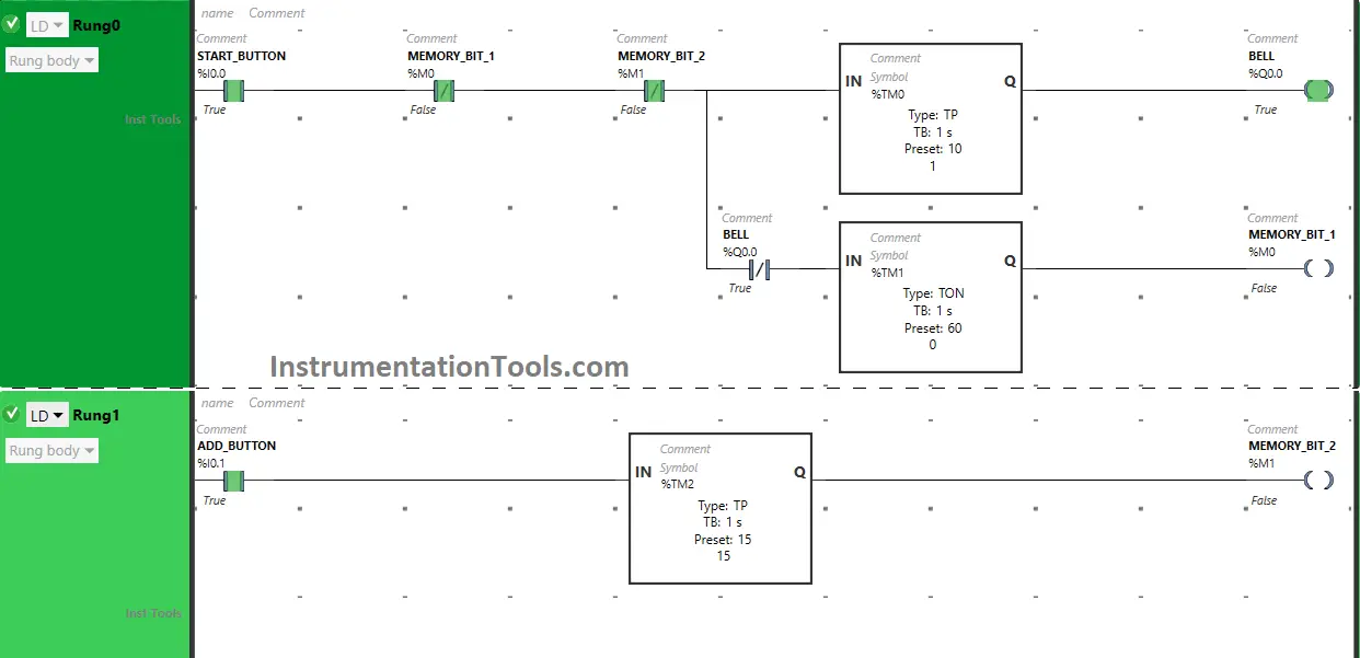
When the Start Button (I0.0) is turned ON, the output Bell (Q0.0) will turn ON for 10 seconds as Timer Function Block type TP is used to Turn ON the output Bell (Q0.0) for a limited time. The time is set to 10 seconds.
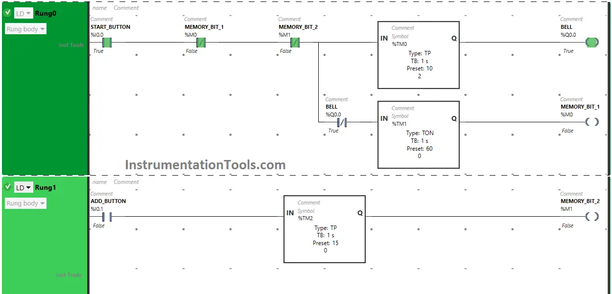
PLC School Automation System

In a false state, Normally Closed Contacts used for Memory Bit 1 (M0) and Memory Bit 2 (M1) pass the signal to turn ON the output Bell (Q0.0).

After 10 seconds, the output Bell (Q0.0) will turn OFF.
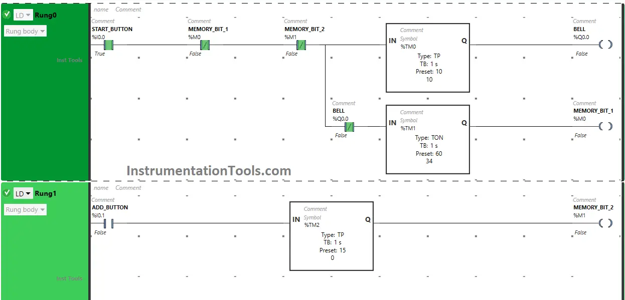
PLC Programming Bell System

Also, when the Start Button (I0.0) is turned ON, Memory Bit 1 (M0) will turn ON after 60 seconds as Timer Function Block TON is used to delay the turning ON time of Memory Bit 1 (M0).

When Memory Bit 1 (M0) turns ON, it will turn OFF immediately as Normally Closed Contact is used for it to turn ON the Output Bell (Q0.0).
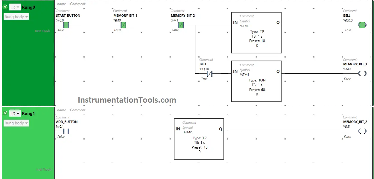
PLC Design of Automatic Bell Ringing System

So, when Memory Bit 1 (M0) turns OFF immediately, Normally Closed Contact used for Memory Bit 1 (M0) again passes the signal to turn the output Bell (Q0.0) for 10 seconds as Timer Function Block type TP is used to Turn ON the output Bell (Q0.0) for a limited time.

When the Add button is turned ON

When the Add Button is turned ON, Memory Bit 2 (M1) will turn ON for 15 seconds as Timer Function Block type TP is used to Turn ON Memory Bit 2 (M1) for a limited time.
Programmable Automatic Bell System

After 15 seconds, Memory Bit 2 (M1) will turn OFF. When Memory Bit (M1) turns ON, Normally Closed Contact used for Memory Bit 2 (M1) will be in True state and Add 15 seconds to delay the turning ON time of the output Bell (Q0.0).

When Timer Function Block type TP reaches its time of 15 seconds, Memory Bit 2 (M1) will turn OFF in Rung1.
College Bell System Ladder Logic

When Memory Bit 2 (M1) turns OFF in Rung1, Normally Closed Contact used for Memory Bit 2 (M1) will be in a false state and allow the signal to pass through it to turn ON the output Bell (Q0.0) and the output (Q0.0) will turn ON.

If you liked this article, please subscribe to our YouTube Channel for PLC and SCADA video tutorials.

You can also follow us on Facebook and Twitter to receive daily updates.

Read Next:

  • Coffee Machine PLC Programming
  • From Boolean Algebra to PLC Logic
  • How to Blink Lights in Ladder Logic?
  • PLC Example on Bottle Line Control
  • Cooking Logic for Kitchen Automation
Don't Miss Our Updates
Be the first to get exclusive content straight to your email.
We promise not to spam you. You can unsubscribe at any time.
Invalid email address
You've successfully subscribed !

Continue Reading

PLC Program – Controls Conveyors ON and OFF Sequence
Allen Bradley PLC ControlLogix Hardware
Ladder Logic for Flow Meter Totalizer
Top 100+ SCADA Questions
HMI Screen Design for Hazardous Applications
Analog Measurement using Ladder Logic
Share This Article
Facebook Whatsapp Whatsapp LinkedIn Copy Link
Share
Leave a Comment

Leave a Reply Cancel reply

Your email address will not be published. Required fields are marked *

Stay Connected

128.3kFollowersLike
69.1kFollowersFollow
210kSubscribersSubscribe
38kFollowersFollow

Categories

Explore More

Concept of DCS in Industrial Automation
How to do Scaling for Analog Input in RSLogix 500?
OB1 – Main Cyclic Organization Block in TIA Portal
PLC Automatic Pedal Switch for Speed Control
Why different PLC Programming Languages were Developed?
PLC Wiring Questions for Technicians and Engineers
What is a Tower Lamp? – Light Tower in Industrial Automation
PLC Programming Videos

Keep Learning

Analog Inputs in Siemens TIA Portal

What are Analog Inputs? – Analog Signals Processing in PLC

Industrial Automation Solution

How to Choose the Right Industrial Automation Solution?

PLC Emergency Stop Example Program

PLC Emergency Stop Example Program

SCADA Run

PLC Based Industrial Conveyor Ladder Logic

Coil Type Timers in Siemens PLC Programming

Coil Type Timers in Siemens PLC Programming

Retentive Timer (RTO)

Timer in Studio 5000 – TON, TOF, RTO

Top PLC Manufacturers

PLC Brands Software Information

How to Detect Speed of Conveyor in PLC

How to Detect Speed of Conveyor in PLC?

Learn More

Control Loops Multiple Choice Questions

Control Loop Multiple Choice Questions

Left-Hand Rule for Generators

Starting of DC Motors

Power Electronics Objective Questions

Thyristors Objective Questions and Answers

Guided-wave Radar Asset Management Parameters

Guided-wave Radar Asset Management Parameters

Comparison of Half wave Rectifiers and Full wave Rectifiers

Comparison of Half wave Rectifiers and Full wave Rectifiers

Fieldbus Segment Design

Foundation Fieldbus Segment Design

Geothermal Energy Power Plants

Geothermal Energy Power Plants

Single Push button to ON and OFF a Bulb using Ladder Logic

Single Push button to ON and OFF a Bulb using Ladder Logic

Menu

  • About
  • Privacy Policy
  • Copyright

Quick Links

  • Learn PLC
  • Helping Hand
  • Part Time Job

YouTube Subscribe

Follow US
All rights reserved. Reproduction in whole or in part without written permission is prohibited.
Welcome Back!

Sign in to your account

Username or Email Address
Password

Lost your password?