Inst ToolsInst ToolsInst Tools
  • Courses
  • Automation
    • PLC
    • Control System
    • Safety System
    • Communication
    • Fire & Gas System
  • Instrumentation
    • Design
    • Pressure
    • Temperature
    • Flow
    • Level
    • Vibration
    • Analyzer
    • Control Valve
    • Switch
    • Calibration
    • Erection & Commissioning
  • Interview
    • Instrumentation
    • Electrical
    • Electronics
    • Practical
  • Q&A
    • Instrumentation
    • Control System
    • Electrical
    • Electronics
    • Analog Electronics
    • Digital Electronics
    • Power Electronics
    • Microprocessor
  • Request
Search
  • Books
  • Software
  • Projects
  • Process
  • Tools
  • Basics
  • Formula
  • Power Plant
  • Root Cause Analysis
  • Electrical Basics
  • Animation
  • Standards
  • 4-20 mA Course
  • Siemens PLC Course
Reading: Connecting Blocks in Functional Block Diagram – Studio 5000
Share
Font ResizerAa
Inst ToolsInst Tools
Font ResizerAa
  • Courses
  • Design
  • PLC
  • Interview
  • Control System
Search
  • Courses
  • Automation
    • PLC
    • Control System
    • Safety System
    • Communication
    • Fire & Gas System
  • Instrumentation
    • Design
    • Pressure
    • Temperature
    • Flow
    • Level
    • Vibration
    • Analyzer
    • Control Valve
    • Switch
    • Calibration
    • Erection & Commissioning
  • Interview
    • Instrumentation
    • Electrical
    • Electronics
    • Practical
  • Q&A
    • Instrumentation
    • Control System
    • Electrical
    • Electronics
    • Analog Electronics
    • Digital Electronics
    • Power Electronics
    • Microprocessor
  • Request
Follow US
All rights reserved. Reproduction in whole or in part without written permission is prohibited.
Inst Tools > Blog > PLC Tutorials > Connecting Blocks in Functional Block Diagram – Studio 5000

Connecting Blocks in Functional Block Diagram – Studio 5000

Get insights on connecting blocks in Functional Block Diagram. Understand the fundamental methods to design programs efficiently.

Last updated: March 15, 2025 9:30 pm
Viral Nagda
PLC Tutorials
No Comments
Share
4 Min Read
SHARE

In the earlier post, we saw how to manage sheets, tags and elements in the functional block diagram of Studio 5000. Now, one main thing that every programmer needs to know in a functional block diagram is how to connect the blocks. Once they are able to know all the rules, they can link and design the program accordingly. That is why, it is necessary to know all the possible options of connecting blocks. In this post, we will see how to connect blocks in the functional block diagram of Studio 5000.

Contents
Connect blocks using wiresConnect blocks using reference elementsConnect blocks using the connector

Connect blocks using wires

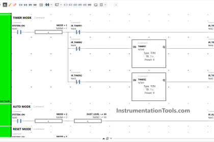
This is the most standard way of connecting blocks. Wire is nothing but a line, which can be drawn to connect the blocks. Refer to the below image. The blue color highlighted is a wire element, which can be drawn to connect the blocks and variables in the sheet.

Connecting Blocks in Functional Block Diagram

When you draw a line and if it is being linked to a wrong pin, it won’t connect and will show you a red mark near the pin. To draw a line, just take your mouse near the pin (it will show a green color if the pin is correct to use) and drag the line to your destination pin. If the destination pin shows a green color, then the line can be drawn.

Connect blocks using reference elements

If it is difficult to draw a line as it is making the whole visuals of the sheet congested, then you can just link the variables to the pin. Refer to the below image. As shown, compare this with the first image we just saw earlier. You can see that in the first image, we drew a line from the timer output to the input pin of the NOT block.

how to connect the blocks in Studio 5000

Instead, we now linked the variable – o_test_op to the input of the NOT block in the below image. The thing is the same; it is just about how to visualize the sheet. But yes, this method will consume some memory, because you are creating a variable specially for this.

Connect blocks using the connector

As sheets are provided, this software provides one interesting feature to interlink the sheets – wire connector. You can link internal tags here, which will not be used by PLC CPU execution. These tags are solely used for interlinking sheets. This means suppose there are 2 sheets. You want to link the output of a block in the first sheet to the input of a block in the second sheet. Instead of creating variables or dynamic linking of block outputs, you can create local variables which will only be used in wire connectors for linking a sheet.

Connect blocks using the connector

These variables will not be written any value by PLC, but just be used for navigating. Refer to the above image for more information. Here, you can see that the timer output in sheet-2 is linked to a timer input in sheet-1 using a tag called link. This tag is static and not written by PLC, but merely used for navigating to a sheet (you can see the link as 1-B1 or 2-C2, with the number denoting sheet number and alphabet denoting object positioning).

With this, we end our series on the functional block diagram language of Studio 5000.

Read Next:

  • How Modbus is used in Industrial Networks?
  • Car Wash Program Functional Block Diagram
  • PLC Techniques for I/O Mapping Procedure
  • Conveyor Speed Logic using the PLC Program
  • PLC Programming for Burglar Alarm Security
Don't Miss Our Updates
Be the first to get exclusive content straight to your email.
We promise not to spam you. You can unsubscribe at any time.
Invalid email address
You've successfully subscribed !

Continue Reading

Cloud-Based SCADA Projects – Try Free Demo Account
Learn PLC in Hindi
All About Fieldbus Protocols
Overview of SIEMENS PLC – S7-1500, S7-1200, S7-400, S7-300
Automatic Curtain Control – PLC Programming Solution
Tank Farm Management System: CX-Programmer [OMRON]
Share This Article
Facebook Whatsapp Whatsapp LinkedIn Copy Link
Share
Leave a Comment

Leave a Reply Cancel reply

Your email address will not be published. Required fields are marked *

Stay Connected

128.3kFollowersLike
69.1kFollowersFollow
210kSubscribersSubscribe
38kFollowersFollow

Categories

Explore More

PLC Programming Example on Timers Function Block
Allen Bradley PLC ControlLogix Hardware
#6 PLC Best Practices – Validate Timers and Counters
Electrical and Instrumentation – Automation Pre-engineering Documents
PLC Programming for Baking with Auto and Manual Modes
Alarm Acknowledge using PLC
PLC Pump Control: 10 seconds ON & 20 seconds OFF
PLC Analog Input Scaling

Keep Learning

Unspecified CPU in Tia Portal

How to Add Unspecified CPU in Tia Portal?

Wiring in PLC System

Wiring in a PLC Control Panel

Faceplates

What are Faceplates? How to Create a Faceplate? HMI Visualization

HMI Simulation for PID Controller

PID Controller Output Types – PID_PWM and PID_Output

PLC Program Example - Signal Lamp Task

PLC Program Examples

Coil Type Timers in Siemens PLC Programming

Coil Type Timers in Siemens PLC Programming

HMI screen for operator

Auto Tiffin Box Filling Station

Example of Controlling the PLC Output using Push Buttons

Example of Controlling the PLC Output using Push Buttons

Learn More

Erratic H2 Flow Rotameter

Erratic H2 Flow Rotameter

How Engineers Effectively do Problem-solve and Troubleshoot

How Engineers Effectively do Problem-solve and Troubleshoot?

Contact less Tachometer

Types of Tachometers – Mechanical and Electrical Tachometers

Diaphragm seal for pressure measurement device

When to use a Diaphragm Seal?

Types of Wireless Technologies in Industrial Automation

Types of Wireless Technologies in Industrial Automation

Valve Position Indication

Valve Position Indication

Load Cell Design

Load Cell Design

SIS Testing and Repair Deferral

SIS Testing and Repair Deferral

Menu

  • About
  • Privacy Policy
  • Copyright

Quick Links

  • Learn PLC
  • Helping Hand
  • Part Time Job

YouTube Subscribe

Follow US
All rights reserved. Reproduction in whole or in part without written permission is prohibited.
Welcome Back!

Sign in to your account

Username or Email Address
Password

Lost your password?