Inst ToolsInst ToolsInst Tools
  • Courses
  • Automation
    • PLC
    • Control System
    • Safety System
    • Communication
    • Fire & Gas System
  • Instrumentation
    • Design
    • Pressure
    • Temperature
    • Flow
    • Level
    • Vibration
    • Analyzer
    • Control Valve
    • Switch
    • Calibration
    • Erection & Commissioning
  • Interview
    • Instrumentation
    • Electrical
    • Electronics
    • Practical
  • Q&A
    • Instrumentation
    • Control System
    • Electrical
    • Electronics
    • Analog Electronics
    • Digital Electronics
    • Power Electronics
    • Microprocessor
  • Request
Search
  • Books
  • Software
  • Projects
  • Process
  • Tools
  • Basics
  • Formula
  • Power Plant
  • Root Cause Analysis
  • Electrical Basics
  • Animation
  • Standards
  • 4-20 mA Course
  • Siemens PLC Course
Reading: Induction Motor
Share
Notification Show More
Font ResizerAa
Inst ToolsInst Tools
Font ResizerAa
  • Courses
  • Design
  • PLC
  • Interview
  • Control System
Search
  • Courses
  • Automation
    • PLC
    • Control System
    • Safety System
    • Communication
    • Fire & Gas System
  • Instrumentation
    • Design
    • Pressure
    • Temperature
    • Flow
    • Level
    • Vibration
    • Analyzer
    • Control Valve
    • Switch
    • Calibration
    • Erection & Commissioning
  • Interview
    • Instrumentation
    • Electrical
    • Electronics
    • Practical
  • Q&A
    • Instrumentation
    • Control System
    • Electrical
    • Electronics
    • Analog Electronics
    • Digital Electronics
    • Power Electronics
    • Microprocessor
  • Request
Follow US
All rights reserved. Reproduction in whole or in part without written permission is prohibited.
Inst Tools > Blog > Electrical Theory > Induction Motor

Induction Motor

Last updated: August 6, 2018 5:10 pm
Editorial Staff
Electrical Theory
No Comments
Share
1 Min Read
SHARE

Induction Motor

Previous explanations of the operation of an AC motor dealt with induction motors. The induction motor is the most commonly used AC motor in industrial applications because of its simplicity, rugged construction, and relatively low manufacturing costs.

The reason that the induction motor has these characteristics is because the rotor is a self-contained unit, with no external connections. This type of motor derives its name from the fact that AC currents are induced into the rotor by a rotating magnetic field.

Squirrel-Cage Induction Rotor

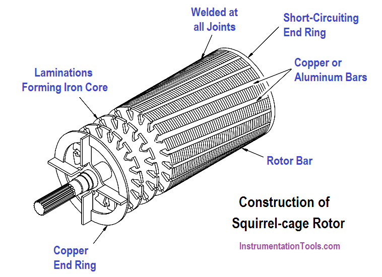
The induction motor rotor (Figure) is made of a laminated cylinder with slots in its surface. The windings in the slots are one of two types. The most commonly used is the “squirrel-cage” rotor. This rotor is made of heavy copper bars that are connected at each end by a metal ring made of copper or brass.

No insulation is required between the core and the bars because of the low voltages induced into the rotor bars. The size of the air gap between the rotor bars and stator windings necessary to obtain the maximum field strength is small.

Squirrel-Cage Induction Motor

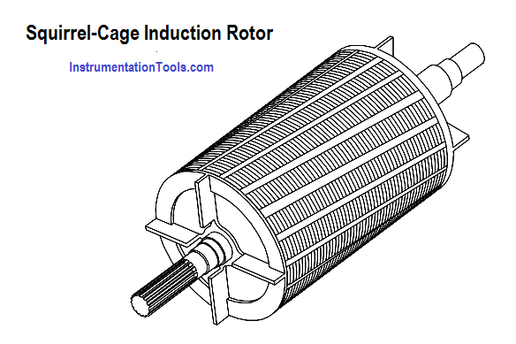
Figure : Squirrel-Cage Induction Rotor

Don't Miss Our Updates
Be the first to get exclusive content straight to your email.
We promise not to spam you. You can unsubscribe at any time.
Invalid email address
You've successfully subscribed !

Continue Reading

AC Induction Motor Slip
AC Motor Theory
Wattmeter
Induction Motor Torque Versus Slip
DC Machines Terminology
Compound Generators
Share This Article
Facebook Whatsapp Whatsapp LinkedIn Copy Link
Share
Leave a Comment

Leave a Reply Cancel reply

Your email address will not be published. Required fields are marked *

Stay Connected

128.3kFollowersLike
69.1kFollowersFollow
210kSubscribersSubscribe
38kFollowersFollow

Categories

Explore More

Units of Electrical Measurement
Three Phase Systems
Thermocouples
Capacitance
Transformer Impedance Ratio
Transformer Current Ratio
Conductor, Insulator, Resistor and Current Flow
Parallel Open Circuit Faults

Keep Learning

Power Factor Meter Principle

Power Factor Meter Principle

Left-Hand Rule for Generators

DC Generator Theory

DC Machine

DC Generator Internal Losses

Generator Action in a Motor

Generator Action in a Motor

Electron Flow Through Battery

Batteries Theory

Current in a Capacitor

Capacitance and Capacitive Reactance

Three Phase To Single Phase Wiring Connections

Single Phase Power Wiring Schemes

Center Tap Full-Wave Rectifier

Full-Wave Rectifier Circuit

Learn More

Allen-Bradley VFD

Motor VFD Drive features

Simulating Level Sensor and the Pump Logic in PLC

PLC Basics – Manual Control, Closed Loop, ON-OFF with Hysteresis

Closed-tank-DP-Level-Transmitter-with-wet-leg-elevation-zero-direct-mount-Calibration

Closed tank DP Level Transmitter with wet leg elevation zero direct mount Calibration

What Happens When a Pump Runs Dry

What Happens When a Pump Runs Dry? How to Avoid it?

Instrument Switch Status

Define Normal Status of a Process Switch ?

Power Electronics Objective Questions

Single-Phase Full Wave AC-DC Converter Questions

Direct & reverse actions control valve

Direct Acting Control Valves & Reverse Acting Control Valves

Optoisolator Working Principle

Optoisolator Working Principle

Menu

  • About
  • Privacy Policy
  • Copyright

Quick Links

  • Learn PLC
  • Helping Hand
  • Part Time Job

YouTube Subscribe

Follow US
All rights reserved. Reproduction in whole or in part without written permission is prohibited.
Welcome Back!

Sign in to your account

Username or Email Address
Password

Lost your password?