Inst ToolsInst ToolsInst Tools
  • Courses
  • Automation
    • PLC
    • Control System
    • Safety System
    • Communication
    • Fire & Gas System
  • Instrumentation
    • Design
    • Pressure
    • Temperature
    • Flow
    • Level
    • Vibration
    • Analyzer
    • Control Valve
    • Switch
    • Calibration
    • Erection & Commissioning
  • Interview
    • Instrumentation
    • Electrical
    • Electronics
    • Practical
  • Q&A
    • Instrumentation
    • Control System
    • Electrical
    • Electronics
    • Analog Electronics
    • Digital Electronics
    • Power Electronics
    • Microprocessor
  • Request
Search
  • Books
  • Software
  • Projects
  • Process
  • Tools
  • Basics
  • Formula
  • Power Plant
  • Root Cause Analysis
  • Electrical Basics
  • Animation
  • Standards
  • 4-20 mA Course
  • Siemens PLC Course
Reading: Understanding a Process Control Loop
Share
Font ResizerAa
Inst ToolsInst Tools
Font ResizerAa
  • Courses
  • Design
  • PLC
  • Interview
  • Control System
Search
  • Courses
  • Automation
    • PLC
    • Control System
    • Safety System
    • Communication
    • Fire & Gas System
  • Instrumentation
    • Design
    • Pressure
    • Temperature
    • Flow
    • Level
    • Vibration
    • Analyzer
    • Control Valve
    • Switch
    • Calibration
    • Erection & Commissioning
  • Interview
    • Instrumentation
    • Electrical
    • Electronics
    • Practical
  • Q&A
    • Instrumentation
    • Control System
    • Electrical
    • Electronics
    • Analog Electronics
    • Digital Electronics
    • Power Electronics
    • Microprocessor
  • Request
Follow US
All rights reserved. Reproduction in whole or in part without written permission is prohibited.
Inst Tools > Blog > Basics > Understanding a Process Control Loop

Understanding a Process Control Loop

Last updated: April 2, 2019 10:19 pm
Editorial Staff
Basics Control Systems
8 Comments
Share
6 Min Read
SHARE

Hi, its me again and I am about to tackle a very important framework in the field of Instrumentation. Assuming you already have read my post regarding what is a process control is and what are the parameters involved in this process. We are now going to learn how these parameters are meet in a process control loop.

First we need to know what are the major components a traditional control loop has.

1. The controller
2. A sensor/transmitter
3. A final control element
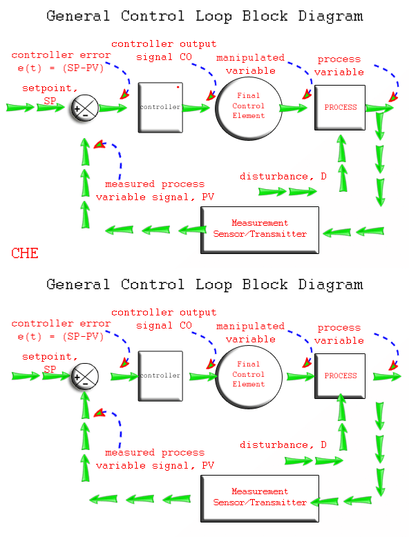
Closed Loop Controller Animation

A controller that seeks to maintain the measured process variable (PV) transmitted by a sensor or a transmitter. and a the final control element that implements in real life the decision or solution taken by the controller. Common examples of a final control element are control valves, relay switches and variable frequency drive to name a few.

To design and implement a controller, we must: have identified a process variable we seek to regulate (e.g., room temperature like in the example mentioned), be able to measure it with a sensor, and be able to transmit that measurement as an electrical signal back to our controller, and have a final control element that can receive the controller output (CO) signal, react in some fashion to impact the process (e.g., a control valve moves or a relay switch turns on/off), and as a result cause the process variable to respond in a consistent and predictable fashion.

As shown below Animation, the home heating control system described by wiki can be organized as a traditional control loop block diagram. Block diagrams help us visualize the components of a loop and see how the pieces are connected.
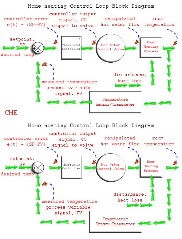
Closed Loop System Working Animation

A home heating system can be a simple on/off control or a proportional control by adjusting the amount of hot fluid by throttling a control valve. Nevertheless, we introduce the idea of control loop diagrams by presenting a home heating system in the same way we would a more sophisticated commercial control application.

A home heating system can be a simple on/off control or a proportional control by adjusting the amount of hot fluid by throttling a control valve. Nevertheless, we introduce the idea of control loop diagrams by presenting a home heating system in the same way we would a more sophisticated commercial control application.

Starting from the far right in the diagram above, our process variable of interest is the house temperature. A temperature sensor, such as a thermistor in a modern digital thermostat, measures temperature and transmits a signal to the controller.

The measured temperature PV signal is subtracted from set point to compute controller error, e(t) = SP – PV. The action of the controller is based on this error, e(t).

In this example,home heating system, the controller output feds a varying or proportional milliamp signal to a variable operating solenoid or servo valve (our Final Control Element)that controls the flow of hot water .

As the energy output of the furnace rises or falls, the temperature of our house increases or decreases and a feedback loop is complete.

The important elements of a home heating control system can be organized like any commercial application:

Control Objective: maintain room temperature at (SP) in spite of disturbances

Process Variable: room temperature

Measurement Sensor: temperature sensor,Thermistor

Measured Process Variable (PV) Signal: signal transmitted from the thermistor

Set Point (SP): desired room temperature

Controller Output (CO) or Manipulated Variable (MV): signal to the variable operating solenoid valve.

Final Control Element (FCE): variable operating solenoid valve to control hot water flow

Manipulated Variable: hot water flow rate to chamber

Disturbances (D): heat loss from doors, walls and windows; changing outdoor temperature; sunrise and sunset; rain…

With the loop closed as shown in the diagrams, we are said to be in automatic mode and the controller is making all adjustments to the Final Control Element. If we were to open the loop and switch to manual mode, then we would be able to issue controller output commands through buttons or a keyboard directly to the Final Control Element.

Therefore:

Open Loop = Manual Mode
Closed Loop = Automatic Mode

This control loop block diagram will be a frame work to more simple process control and even to more sophisticated commercial control application. I hope you learned something. jump in to more of my posts.
Don't Miss Our Updates
Be the first to get exclusive content straight to your email.
We promise not to spam you. You can unsubscribe at any time.
Invalid email address
You've successfully subscribed !

Continue Reading

Capacitive Coupling Effects
What is Override Control? – Need & Applications
What is the DDE Protocol?
Industry 4.0 Explained – Industrial Internet of Things
Project Planning and Implementation of PLC or DCS Control System
What is WHCP?
Share This Article
Facebook Whatsapp Whatsapp LinkedIn Copy Link
Share
8 Comments
  • Varun P says:
    June 17, 2015 at 6:50 pm

    Outstanding & Simple Explanation.

    Reply
  • RNkhan says:
    August 21, 2015 at 11:33 am

    Good animation about control loop

    Reply
  • Shaju says:
    September 13, 2015 at 2:46 pm

    Good explanation.
    Thanks for the information

    Reply
  • senthil kumar says:
    August 11, 2016 at 6:33 pm

    Nicely Explained

    Reply
  • ojo samuel says:
    July 10, 2017 at 3:22 pm

    thanks in milloins

    Reply
  • Blueasea says:
    December 9, 2019 at 10:45 pm

    Thanks a lot, very easy to understand

    Reply
  • Isaac says:
    April 24, 2021 at 2:34 pm

    Thanks a lot. This is very helpful, simple and understandable

    Reply
  • Sujit says:
    March 24, 2023 at 7:53 pm

    Thanks a lot

    Reply

Leave a Reply Cancel reply

Your email address will not be published. Required fields are marked *

Stay Connected

128.3kFollowersLike
69.1kFollowersFollow
210kSubscribersSubscribe
38kFollowersFollow

Categories

Explore More

How to Tune a Loop in DeltaV System
ICS Control System Security
Problem in Water Level Control System
Augmented Reality and Virtual Reality in Industrial Automation
Industrial Networking and Wireless Interview Questions
Setpoints and Alarms in Control System
PID Controller Loop Tuning Tips
What is Feedforward Control ?

Keep Learning

DCS

DCS

Ziegler-Nichols open-loop Tuning

Ziegler-Nichols Open-Loop Method

Proportional Control Theory

Proportional-only Offset

Instrumentation Engineer Interview Questions

Interview Questions on PID Controllers

Alarm Chattering

Categorization of Alarms in a Process Plant

MODBUS ASCII Communication Protocol Explained

MODBUS ASCII Communication Protocol Explained

2 wire transmitter current loops

2-wire Transmitters Current Loops

annunciator-alarm-simulator

Alarm Simulator for Annunciator Logic

Learn More

Self-balancing Pneumatic Instrument Principles - 3

Self-balancing Pneumatic Instrument Principles

IR Instrumentation Questions & Answers

IR Instrumentation Questions & Answers

Electromagnetic Fields Objective Questions

Electromagnetic Fields Objective Questions

Top Free PLC Software

Top Free PLC Software

Free WinCC SCADA Training Course

Free SCADA Training Course

Capacitor Filter Operation

Capacitor Filter Operation

Power Electronics Objective Questions

Interconnecting Thyristors Objective Questions and Answers

Emergency Shutdown Button Installation (ESD)

Understanding Emergency Shutdown Button Installation (ESD)

Menu

  • About
  • Privacy Policy
  • Copyright

Quick Links

  • Learn PLC
  • Helping Hand
  • Part Time Job

YouTube Subscribe

Follow US
All rights reserved. Reproduction in whole or in part without written permission is prohibited.
Welcome Back!

Sign in to your account

Username or Email Address
Password

Lost your password?