Inst ToolsInst ToolsInst Tools
  • Courses
  • Automation
    • PLC
    • Control System
    • Safety System
    • Communication
    • Fire & Gas System
  • Instrumentation
    • Design
    • Pressure
    • Temperature
    • Flow
    • Level
    • Vibration
    • Analyzer
    • Control Valve
    • Switch
    • Calibration
    • Erection & Commissioning
  • Interview
    • Instrumentation
    • Electrical
    • Electronics
    • Practical
  • Q&A
    • Instrumentation
    • Control System
    • Electrical
    • Electronics
    • Analog Electronics
    • Digital Electronics
    • Power Electronics
    • Microprocessor
  • Request
Search
  • Books
  • Software
  • Projects
  • Process
  • Tools
  • Basics
  • Formula
  • Power Plant
  • Root Cause Analysis
  • Electrical Basics
  • Animation
  • Standards
  • 4-20 mA Course
  • Siemens PLC Course
Reading: PLC Commissioning and Testing Procedure (Programmable Logic Controller)
Share
Font ResizerAa
Inst ToolsInst Tools
Font ResizerAa
  • Courses
  • Design
  • PLC
  • Interview
  • Control System
Search
  • Courses
  • Automation
    • PLC
    • Control System
    • Safety System
    • Communication
    • Fire & Gas System
  • Instrumentation
    • Design
    • Pressure
    • Temperature
    • Flow
    • Level
    • Vibration
    • Analyzer
    • Control Valve
    • Switch
    • Calibration
    • Erection & Commissioning
  • Interview
    • Instrumentation
    • Electrical
    • Electronics
    • Practical
  • Q&A
    • Instrumentation
    • Control System
    • Electrical
    • Electronics
    • Analog Electronics
    • Digital Electronics
    • Power Electronics
    • Microprocessor
  • Request
Follow US
All rights reserved. Reproduction in whole or in part without written permission is prohibited.
Inst Tools > Blog > PLC Tutorials > PLC Commissioning and Testing Procedure (Programmable Logic Controller)

PLC Commissioning and Testing Procedure (Programmable Logic Controller)

In this article, we will discuss the commissioning and testing procedure of PLC (Programmable Logic Controller).

Last updated: September 28, 2022 4:10 pm
Viral Nagda
PLC Tutorials
1 Comment
Share
6 Min Read
SHARE

In this article, we will discuss the commissioning and testing procedure of PLC (Programmable Logic Controller).

Various first-time programmers of industrial automation face a question on what to do when they are asked to test a PLC and its logic properly.

Well, it is obvious because every new task requires some set of rules and steps to follow for proper execution. So, commissioning a PLC is also a tedious task for a new programmer.
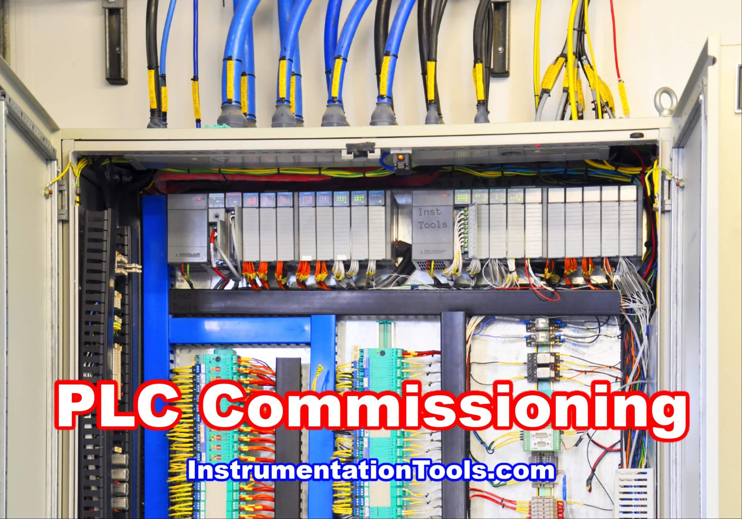
PLC Commissioning

In this post, we will see some general guidelines regarding the commissioning of a PLC. Using these, any new programmer can easily test a PLC and its logic afterward.

PLC Commissioning and Testing

Let us have a look at the below steps.

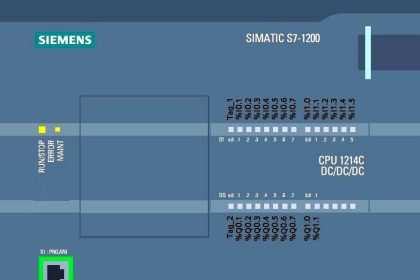
Every PLC has its own software. You are given a PLC and just by starting it, you will not be able to identify what type of software to use.

So, when given a PLC, first check its software version and firmware version on the internet. When you get the latest one, download it to your PC / laptop and install it. The software will also by default install communication drivers along with it, or you will need to manually install it.

Once downloaded, install the software and its communication drivers. When the software is installed, you will be able to select the PLC model number that you have. If the model number is shown correctly, that means the software you have installed is correct.

Once confirmed, you have to start building your PLC program in it. Also, configure the hardware of PLC in the program inside.

After building, compile the program and check for any errors. The program will not be downloaded in PLC if there are compilation errors.

Now, you have to check the wiring of inputs, outputs, and communication ports.

Open the PLC hardware catalog for reference.

Determine whether the PLC inputs are sink or source;

PLC outputs are triac, transistor, or relay type, analog inputs are 4-20 mA or 0-10 V, and analog inputs are 4-20 mA or 0-10 V. Once confirmed, do the necessary wiring in the PLC.

Now that your program is ready and wiring has also been done, take the PLC and power it up according to the supply it requires.

Make sure you also provide proper earthing to the PLC panel.

After powering up, you have to connect the communication cable to it according to the medium you have set in the backup for downloading.

For example, you have set the medium as USB, connect a USB cable to it and see whether its driver is showing the proper name in the computer driver sheet or not. If it is not showing properly or not installed, then you have to reinstall the driver and look for any other updated driver on the internet and use it.

If your connection has been established successfully, go online in the PLC through it now.

First, download the latest firmware in the PLC. After the firmware has been downloaded, power reboot the PLC and then, download your final program in it.

After downloading, put the PLC in run mode.

Now that your PLC is loaded with the program, you now have to check the inputs, outputs, and communication ports.

According to the PLC wiring that you have done, check digital inputs first.

On giving the input, the corresponding PLC input address in the program must be turned on.

Then, check the digital outputs. According to the PLC output address that you have turned on, the physical PLC output must also turn on. When it is ON, check the output voltage across it.

Then, check the analog inputs. On giving the input, the corresponding PLC input address in the program must be shown analog counts accordingly.

Then, check the analog outputs. According to the PLC output address that you have given counts, the physical PLC output must also give the corresponding counts.

After the IO’s have been checked, check the communication ports configured in PLC. See whether they are communicating or not.

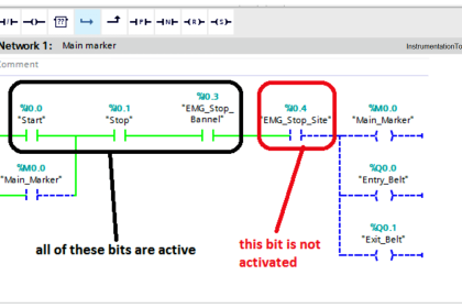
Now, check the program that you have developed and see whether it is functioning according to the IO’s configured. If done, your PLC is commissioned now.

In this way, we saw how to commission a PLC.

If you liked this article, then please subscribe to our YouTube Channel for Instrumentation, Electrical, PLC, and SCADA video tutorials.

You can also follow us on Facebook and Twitter to receive daily updates.

Read Next:

  • Errors in Siemens PLC
  • DCS Commissioning
  • Learn SCADA System
  • Electrical Wiring Diagram
  • Yokogawa DCS Tutorials
Don't Miss Our Updates
Be the first to get exclusive content straight to your email.
We promise not to spam you. You can unsubscribe at any time.
Invalid email address
You've successfully subscribed !

Continue Reading

Hardware Troubleshooting Steps for PLC Automation Systems
Wood Sawing and Blower System: PLC Control Design
GET Command – Siemens PLC-to-PLC Communication Project
PLC System Documentation
Comparison Instructions in PLC Programming
Auto Sugar Bag Filling Station
Share This Article
Facebook Whatsapp Whatsapp LinkedIn Copy Link
Share
1 Comment
  • Asiku Godwin says:
    February 20, 2022 at 1:33 pm

    Good

    Reply

Leave a Reply Cancel reply

Your email address will not be published. Required fields are marked *

Stay Connected

128.3kFollowersLike
69.1kFollowersFollow
210kSubscribersSubscribe
38kFollowersFollow

Categories

Explore More

RSLogix 5000 PLC Programming Procedure
SCADA Communication and Protocols
If Else Statement in SCL Language
PLC SCL Program for Marking Machine
Function of Racks in PLC – Types of SIEMENS S7-400 PLC Racks
100 PLC Quiz Questions : True or False
Basics of PLC Programming
CX Programmer Example: Perfume Mixing and Filling System

Keep Learning

Alarm and Trip Documentation

PLC Alarm and Trip Documentation

Peripheral Inputs and Outputs in Siemens PLC

Peripheral Inputs and Outputs in Siemens PLC

Siemens TIA Portal program blocks

Tia Portal – Optimized and Standard Data Block Access

HMI Screen Design for Hazardous Applications

HMI Screen Design for Hazardous Applications

Encode and Decode Instructions

How to Use Encode and Decode Instructions in PLC ?

PLC Cooking Timer Example for Kitchen Automation

PLC Cooking Timer Example for Kitchen Automation

Allen-Bradley PLC

#15 PLC Best Practices – Safe State when PLC Restarts

Machine Indicator Lights PLC Programming Solution

Machine Indicator Lights: PLC Programming Solution

Learn More

Transparent Level Gauge

Level Indicators Working Principle

Humidity Sensing Absorption Hydrometer Principle

Humidity Sensing Absorption Hydrometer Principle

process chemical analyzer calibration

Automated Calibration

Circular chart recorder Applications

What is Circular Chart Recorder?

Radiochemical Questions and Answers

Gamma Camera Questions & Answers

Bagging Machine Controller

Bagging Machine Controller – Principle, Operation Sequence

Ozone analyzer principle

Ozone Analyzer Working Principle

Siemens PCS 7

What is PCS 7?

Menu

  • About
  • Privacy Policy
  • Copyright

Quick Links

  • Learn PLC
  • Helping Hand
  • Part Time Job

YouTube Subscribe

Follow US
All rights reserved. Reproduction in whole or in part without written permission is prohibited.
Welcome Back!

Sign in to your account

Username or Email Address
Password

Lost your password?