In this article, we discussed Encode (ENC) and Decode (DCD) Instructions application in PLC ladder logic with example programs.
In telecommunication, multiple analog and digital signals are combined into one signal over a shared medium. The multiplexed signal is transmitted over a communication channel such as a cable.
The multiplexing divides the capacity of the communication channel into several logical channels, one for each message signal or data stream to be transferred.
A reverse process, known as demultiplexing, extracts the original channels on the receiver end.
Encode and Decode Instructions

ENCODING (ENC)
Source is the address of the word to be encoded. Only one bit of this word should be on at any one time.
If more than one bit in the source is set, the destination bits will be set based on the least significant bit that is set. If a source of zero is used, all of the destination bits will be reset and the zero bit will be set.
Destination is the address that contains the bit encode information. Bits 4 -15 of the destination are reset by the ENC instruction.
DECODING (DCD)
Use DCD output instruction to multiplex data for applications such as rotary switches, keypads, bank switching, etc.
When rung conditions are true, the DCD instruction decodes a 4-bit value (0-16) in the source word and turns on a bit in the destination word that corresponds to the decoded value.
Source is the address that contains the bit decode information. Only the first four bits (0-3) are used. The remaining bits may be used for other application specific needs. Change the value of the first four bits of this word to select one bit of the destination word.
Destination is the address of the word to be decoded. Only one bit of this word is turned on at any one time, depending on the value of the source word,
PLC Program

Program Description
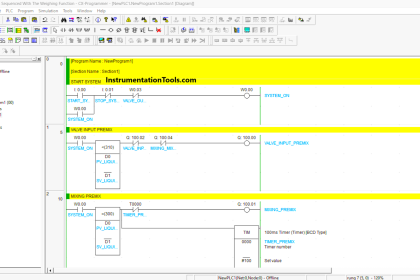
- RUNG 000 – I:0/0 is used to enable the rung condition, ENC block is used to encode the data from B3:0 and store the result in B3:1.
- RUNG 001 – I:0/1 is used to enable the rung condition, DCD block is used to decode the data from B3:2 and store the result in B3:3.
EXAMPLE 1 :
ENCODING
SOURCE : B3:0-1000000000000000 (Any one bit of 16 bit enable to change last four bit of data in destination address)
DESTINATION : B3:1-0000000000001111
DECODING
SOURCE : B3:2-0000000000001111 (Last four bit in source data will change the 16bit data in the destination address)
DESTINATION : B3:3-1000000000000000

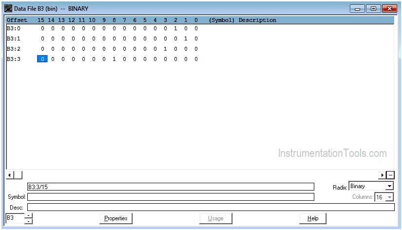
DATA FILE OUTPUT

EXAMPLE 2:
ENCODING
SOURCE : B3:0-0000000000000100 (Any one bit of 16 bit enable to change last four bit of data in destination address)
DESTINATION : B3:1-0000000000000010
DECODING
SOURCE : B3:2-0000000000001000 (Last four bit in source data will change the 16bit data in the destination address)
DESTINATION : B3:3-0000000100000000

DATA FILE OUTPUT
Conclusion:
The above-explained Encode/Decode is for example only. It may vary from real-time.
Author: Hema Sundaresan
If you liked this article, then please subscribe to our YouTube Channel for PLC and SCADA video tutorials.
You can also follow us on Facebook and Twitter to receive daily updates.
Read Next: