Inst ToolsInst ToolsInst Tools
  • Courses
  • Automation
    • PLC
    • Control System
    • Safety System
    • Communication
    • Fire & Gas System
  • Instrumentation
    • Design
    • Pressure
    • Temperature
    • Flow
    • Level
    • Vibration
    • Analyzer
    • Control Valve
    • Switch
    • Calibration
    • Erection & Commissioning
  • Interview
    • Instrumentation
    • Electrical
    • Electronics
    • Practical
  • Q&A
    • Instrumentation
    • Control System
    • Electrical
    • Electronics
    • Analog Electronics
    • Digital Electronics
    • Power Electronics
    • Microprocessor
  • Request
Search
  • Books
  • Software
  • Projects
  • Process
  • Tools
  • Basics
  • Formula
  • Power Plant
  • Root Cause Analysis
  • Electrical Basics
  • Animation
  • Standards
  • 4-20 mA Course
  • Siemens PLC Course
Reading: PLC Alarm and Trip Documentation
Share
Notification Show More
Font ResizerAa
Inst ToolsInst Tools
Font ResizerAa
  • Courses
  • Design
  • PLC
  • Interview
  • Control System
Search
  • Courses
  • Automation
    • PLC
    • Control System
    • Safety System
    • Communication
    • Fire & Gas System
  • Instrumentation
    • Design
    • Pressure
    • Temperature
    • Flow
    • Level
    • Vibration
    • Analyzer
    • Control Valve
    • Switch
    • Calibration
    • Erection & Commissioning
  • Interview
    • Instrumentation
    • Electrical
    • Electronics
    • Practical
  • Q&A
    • Instrumentation
    • Control System
    • Electrical
    • Electronics
    • Analog Electronics
    • Digital Electronics
    • Power Electronics
    • Microprocessor
  • Request
Follow US
All rights reserved. Reproduction in whole or in part without written permission is prohibited.
Inst Tools > Blog > Control Systems > PLC Alarm and Trip Documentation

PLC Alarm and Trip Documentation

Last updated: March 4, 2021 4:57 pm
Editorial Staff
Control Systems PLC Tutorials
1 Comment
Share
3 Min Read
SHARE

A vast amount of documentation is required for the design and construction of a process facility, which are front-end and detailed engineering drawings.

The main engineering documents used on a regular basis by the engineering staff for smooth and efficient running, maintenance, and upgrading of the facility are Alarm and Trip Systems, PLC documentation, and Pipe and Instrumentation Diagrams (P&ID).

As in all engineering disciplines, the initial accuracy of these documents, and the regular updating of them when changes are made, is critical, and one of the most important aspects of engineering.

Documentation standards and symbols for all aspects of process control have been set up and standardized by the ISA, in conjunction with the ANSI.

Alarm and Trip Documentation

PLC Alarm and Trip Documentation

Good, up-to-date documentation is a prerequisite in alarm and trip systems, and must be initiated at the design stage. Hazard analysis must be performed on the facility to determine all areas that require alarms or trips.

The SIS devices should be clearly marked and numbered. System drawings must show all SIS devices using standard symbols, their locations, functions, and set limits. Drawings must include lock and logic diagrams.

The types of information required in Alarm and Trip documentation are:

1. Safety requirement specifications;
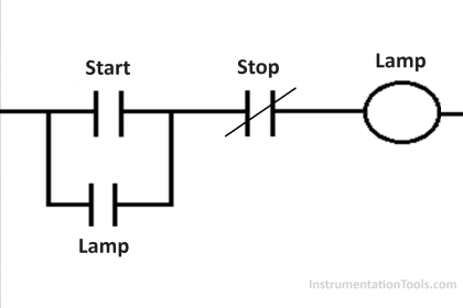
2. Logic diagram with functional description;
3. Functional test procedures and required maintenance;
4. Process monitoring points and trip levels;
5. Description of SIS action if tripped;
6. Action to be taken if SIS power is lost;
7. Manual shutdown procedures;
8. Time requirements to reach safe status;
9. Restarting procedures after SIS shutdown.

Test procedures are needed to verify operation of the total SIS. These procedures must not pose any hazards or cause spurious trips, and must have the ability to detect wear, slow operation, leaking shutoffs, and sticking devices.

A test procedure is necessary for an SIS, and should be available for all alarm and trip devices.

The test procedure should contain the following information:

1. Frequency of testing;
2. Hazards that may be encountered;
3. Drawing and specification information;
4. Test equipment;
5. Performance limits;
6. Test procedure.

The results of the system testing must record any problem areas found, and the corrective action taken.

Typical SIS test results will have the following information:

1. Time and date of test;
2. Test personnel;
3. System identification;
4. Test procedure;
5. Results of test;
6. Corrective action taken;
7. Follow-up required;
8. SIS operational.

Share via Comments, if anything missed above

Article Shared by : V Manikanta

If you liked this article, then please subscribe to our YouTube Channel for PLC and SCADA video tutorials.

You can also follow us on Facebook and Twitter to receive daily updates.

Read Next:

  • Documentation of PLC
  • PLC System Documents
  • Alarm and Trip Systems
  • Basics of Alarms and Trips
Don't Miss Our Updates
Be the first to get exclusive content straight to your email.
We promise not to spam you. You can unsubscribe at any time.
Invalid email address
You've successfully subscribed !

Continue Reading

4-wire Passive versus Active Transmitters
Standard Colors in PLC Automation Systems
How to Write a Program in Ecostruxure Machine Expert HVAC Software?
Automated Garage Gate Control – PLC Ladder Logic
Doll Claw Machine using Omron PLC Programming
PLC Ladder Logic for Start-up Control of Boilers
Share This Article
Facebook Whatsapp Whatsapp LinkedIn Copy Link
Share
1 Comment
  • shubham parit says:
    February 13, 2020 at 10:16 pm

    Nice

    Reply

Leave a Reply Cancel reply

Your email address will not be published. Required fields are marked *

Stay Connected

128.3kFollowersLike
69.1kFollowersFollow
210kSubscribersSubscribe
38kFollowersFollow

Categories

Explore More

PLC Configuration of Profinet I/O System
PLC Based Product Sorting Machine System – Lift Control
Distributed IO Sharing Between PLC Systems – Technical Insights
Comparing ICS and IT Systems Security
PLC Automatic Irrigation System
Vijeo Designer software – Import and Export
Various Control Methods in Servo Motor Drives
Why Are Charcoal and Salt Added to an Earthing Pit?

Keep Learning

Web SCADA HMI

Web-based SCADA HMI Software

What is a function call in TIA Portal

Difference Between FC and FB in Tia Portal

Field Instruments

#11 PLC Best Practices – Instrument for Plausibility Checks

liquid flow control loop

Liquid Flow Control Loop Controller Action

PLC Program Example - Signal Lamp Task

PLC Program Examples

Simple Loop with Local Indication

Instrument Loop Test Requirements and Operation Procedures

PLC Program for Valves

PLC Pump Permissive Interlocks

PLC Interlock Example

PLC Interlock Logic with First Input Priority

Learn More

PLC Automatic Irrigation System Ladder Logic Project

PLC Automatic Irrigation System

Pressure gauge is subjected to five different pressures

How a Bourdon Tube Pressure Gauge might be Adjusted for Linearity?

Pressure Reducing and Desuperheating Station (PRDS)

Pressure Reducing and DeSuperheating Station (PRDS)

Control Speed of an Induction Motor using Analog Output of PLC

Control Speed of Induction Motor using Analog Output of PLC

Control System Vendor Internal Test Procedures

Vendor View of Supplying Industrial Process Control & Safety Systems

Power Electronics Objective Questions

Thyristors Mock Test

Differential Pressure Flow Meters

Short Notes on Differential Pressure Flow Meters

Measurement of Resistance Objective Questions

Measurement of Resistance Objective Questions

Menu

  • About
  • Privacy Policy
  • Copyright

Quick Links

  • Learn PLC
  • Helping Hand
  • Part Time Job

YouTube Subscribe

Follow US
All rights reserved. Reproduction in whole or in part without written permission is prohibited.
Welcome Back!

Sign in to your account

Username or Email Address
Password

Lost your password?