Inst ToolsInst ToolsInst Tools
  • Courses
  • Automation
    • PLC
    • Control System
    • Safety System
    • Communication
    • Fire & Gas System
  • Instrumentation
    • Design
    • Pressure
    • Temperature
    • Flow
    • Level
    • Vibration
    • Analyzer
    • Control Valve
    • Switch
    • Calibration
    • Erection & Commissioning
  • Interview
    • Instrumentation
    • Electrical
    • Electronics
    • Practical
  • Q&A
    • Instrumentation
    • Control System
    • Electrical
    • Electronics
    • Analog Electronics
    • Digital Electronics
    • Power Electronics
    • Microprocessor
  • Request
Search
  • Books
  • Software
  • Projects
  • Process
  • Tools
  • Basics
  • Formula
  • Power Plant
  • Root Cause Analysis
  • Electrical Basics
  • Animation
  • Standards
  • 4-20 mA Course
  • Siemens PLC Course
Reading: Wood Sawing and Blower System: PLC Control Design
Share
Notification Show More
Font ResizerAa
Inst ToolsInst Tools
Font ResizerAa
  • Courses
  • Design
  • PLC
  • Interview
  • Control System
Search
  • Courses
  • Automation
    • PLC
    • Control System
    • Safety System
    • Communication
    • Fire & Gas System
  • Instrumentation
    • Design
    • Pressure
    • Temperature
    • Flow
    • Level
    • Vibration
    • Analyzer
    • Control Valve
    • Switch
    • Calibration
    • Erection & Commissioning
  • Interview
    • Instrumentation
    • Electrical
    • Electronics
    • Practical
  • Q&A
    • Instrumentation
    • Control System
    • Electrical
    • Electronics
    • Analog Electronics
    • Digital Electronics
    • Power Electronics
    • Microprocessor
  • Request
Follow US
All rights reserved. Reproduction in whole or in part without written permission is prohibited.
Inst Tools > Blog > PLC Tutorials > Wood Sawing and Blower System: PLC Control Design

Wood Sawing and Blower System: PLC Control Design

In this article, you will learn the wood sawing and blower system automation and explained the PLC control design.

Last updated: May 1, 2024 2:26 pm
Editorial Staff
PLC Tutorials
No Comments
Share
7 Min Read
SHARE

In this article, you will learn the wood sawing and blower system automation and explained the PLC control design.

Contents
Wood Sawing and Blower SystemPLC Control DesignInputs and OutputsLadder LogicProgram ExplanationSimulation Results

Note: This PLC logic is prepared for learning purposes and can be used to learn ladder logic programming.

Wood Sawing and Blower System

Problem Statement:

Design a PLC ladder logic for the following application.

We are using one Push Button and one sensor to control wood sawing and blower (fan).

The Sawing operation takes place for 10 seconds when the push button is pressed and the wood is placed there.

After the sawing operation is Complete, the wood is removed, and a blower (fan) is used to blow away the sawdust which remains activated for 5 seconds.

PLC Control Design

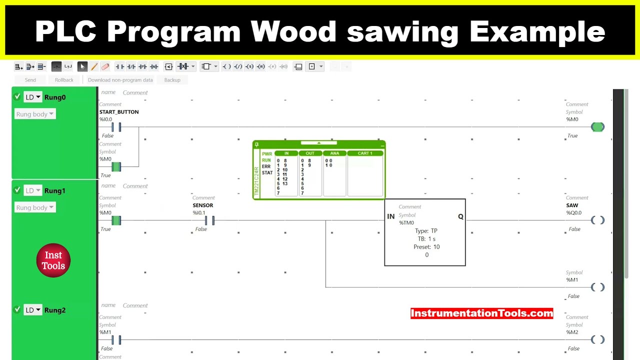
This video explains the PLC control programming with full details.

PLC Programming Wood Sawing Example

Inputs and Outputs

Digital Inputs:

Start Button: I0.0

Sensor: I0.1

Digital Outputs:

Saw: Q0.0

Fan: Q0.1

Ladder Logic
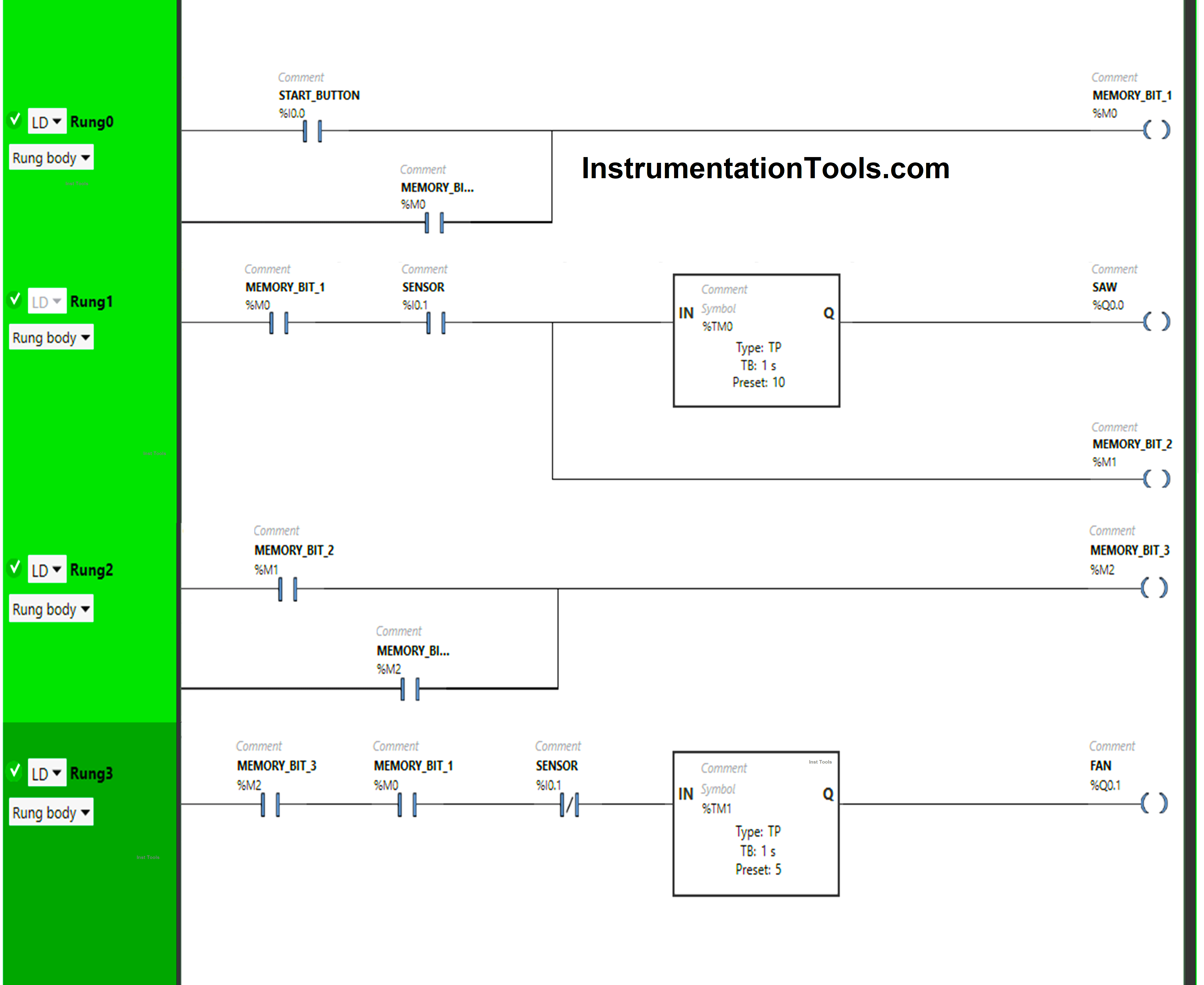
Wood Sawing and Blower System PLC Control Design

Program Explanation

We have used Normally Open Contacts for Start Button (I0.0), Sensor (I0.1), and Memory Bits.

We have used Normally Closed Contact for Sensor (I0.1)

In Rung 0:

  1. Normally Open Contact is used for the Start Button(I0.0) to Turn ON Memory Bit 1 (M0).
  2. Memory Bit 1 (M0) is latched so that when the Start Button (I0.0) turns OFF, Memory Bit 1 (M0) still remains ON.

In Rung 1:

  1. Normally Open Contacts are used for Memory Bit 1 (M0) and Sensor (I0.1) to Turn ON the output Saw (I0.1) and Memory Bit 2 (M1).
  2. Timer Function Block type TP is used to Turn ON the output Saw (Q0.0) for a limited time.

In Rung 2:

  1. Normally Open Contact is used for Memory Bit 2 (M1) to Turn ON Memory Bit 3 (M2).
  2. Memory Bit 3 (M2) is latched so that Memory Bit 2 (M1) turns OFF, and Memory Bit 3 (M2) still remains ON.

In Rung 3:

  1. Normally Open Contacts are used for Memory Bit 1 (M0) and Memory Bit 3 (M2) to turn ON the output Fan (Q0.1).    
  2. Normally Closed Contact is used for the Sensor (I0.1) to Turn ON the output Fan (Q0.1).
  3. Timer Function Block type TP is used to Turn ON the output Fan (Q0.1) for a limited time.

Simulation Results

We simulate the PLC program and discuss the results. We show the partial logic in the test cases instead of the complete program. We recommend you to refer to the above video.

Rung 0 (When Start Button is Pressed):

When the Start Button (I0.0) is pressed and released,  Memory Bit 1 (M0) turns ON and stores the data that the Start Button (I0.0) is pressed as Memory bits store the data.

PLC Programming Wood Sawing Example

Memory Bit 1 (M0) is latched so that when the Start Button (I0.0) is released, Memory Bit 1 (M0) still remains ON.

Wood saw cutter PLC program

Rung 1 (When Sensor gets Activated):

When Memory Bit 1 (M0) turns ON in Rung0, Normally Open Contact used for Memory Bit 1 (M0) in Rung1 will be in True State and will pass the signal to pass through it.

PLC Program of SAW Cutting Machine

When Sensor (I0.1) gets activated (Sensor detects wood), the output Saw (Q0.0) turns ON (Sawing Operation starts), and Memory Bit 2 (M1) turns ON.

The output Saw (Q0.0) will turn OFF after some time as Timer Function Type TP is used to turn ON the output Saw (Q0.0) for a limited time. The time is set to 10 seconds.

After 10 seconds, the output Saw (Q0.0) turns OFF (Sawing operation finishes).

PLC for Automatic Cutting Machine

Rung 2:

When Memory Bit 2 (M1) turns ON in Rung1, Normally Open Contact used for Memory Bit 2 (M1) in Rung2 will be in True State and will pass the signal to turn ON Memory Bit 3 (M2).

Automated Sawing and Dust Removal

Memory Bit 3 (M2) is latched so that when Memory Bit 2 (M1) turns OFF, Memory Bit 3 (M2) still remains ON.

Rung 3 (When Sensor gets deactivated):

When Memory Bit 1 (M0) turns ON in Rung0 and Memory Bit 3 (M2) turns ON in Rung2, Normally Open Contacts used for Memory Bit 1 (M0) and Memory Bit 3 (M2) in Rung3 will be in True State, and will pass the signal to pass through it.

Sawing and Blowing PLC Program

When Sensor (I0.1) gets deactivated (Sensor does not detect wood or Wood is removed after Sawing Operation), the output Fan (Q0.1) turns ON ( Fan starts)as Normally Closed Contact used for Sensor (I0.1) will be in False state and passes the signal to turn ON the output Fan (Q0.1) and the output Fan (Q0.1) turns ON.

The output Fan (Q0.1) will turn OFF after some time as Timer Function Type TP is used to turn ON the output Fan (Q0.1) for a limited time. The time is set to 5 seconds. After 5 seconds, the output Fan (Q0.1) turns OFF (Fan stops).
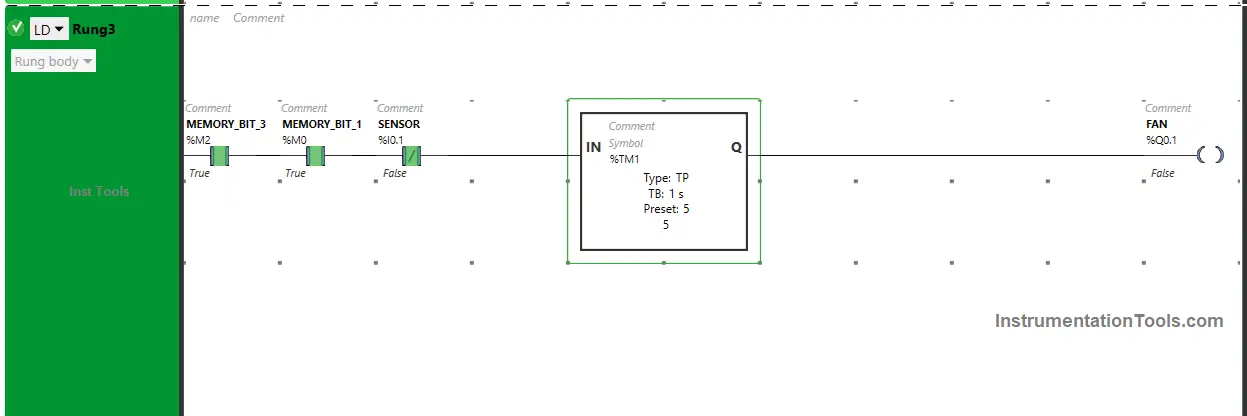
Woodworking Automation PLC Logic

If you liked this article, please subscribe to our YouTube Channel for PLC and SCADA video tutorials.

You can also follow us on Facebook and Twitter to receive daily updates.

Read Next:

  • Ladder Logic Program for Push Button and Motor
  • Conveyor Operation with a Backup Motor using PLC
  • PLC Program for Gas Pressure Closed-Loop Control
  • Electrical Machines Objective Questions and Answers
  • Industrial Drives Objective Questions and Answers
Don't Miss Our Updates
Be the first to get exclusive content straight to your email.
We promise not to spam you. You can unsubscribe at any time.
Invalid email address
You've successfully subscribed !

Continue Reading

T Flip Flop PLC Ladder Diagram
PLC Programming to Control Lights in a Sequence
PLC Program for Continuous Filling Operation
PLC Conveyor Ladder Logic Program
SFC Language in PLC Programming
Applications of SCADA
Share This Article
Facebook Whatsapp Whatsapp LinkedIn Copy Link
Share
Leave a Comment

Leave a Reply Cancel reply

Your email address will not be published. Required fields are marked *

Stay Connected

128.3kFollowersLike
69.1kFollowersFollow
210kSubscribersSubscribe
38kFollowersFollow

Categories

Explore More

PLC to PLC Communication using S7 Connection PUT & GET Instructions
PID Controllers in Closed Loop Control Systems – PLC Basics
PLC Program to Simulate Gate Array Logic
Structured Text PLC Example for Motor Interlocking and Control
Configuration of InTouch Scada Trends
4–20 mA Process Control Loops
PLC Logic Functions
How to Configure IP Address in Rockwell PLC?

Keep Learning

Delta WPL Soft Counter

Delta PLC Counter with Comparison

Concept of Interlocking in PLC

Concept of Interlocking in PLC

Omron PLC Online Training Course

Omron PLC Online Training Course

PLC Program for Car Parking

PLC Program for Entry and Exit Control of Car Parking

Open Platform Communication (OPC)

Open Platform Communication (OPC)

PLC Programmer Salary and Future Career Scope

PLC Programmer Salary and Future Career Scope

Electrical Ladder Diagram Control using Timers Example

Electrical Ladder Diagram Control using Timers Example

Functional block diagram for analog alarms

PLC Logic for Analog Alarms using Functional Block Diagram

Learn More

Electromagnetic Noise Interference

What is Electromagnetic Noise Interference?

DC Machine

DC Generator Internal Losses

Proximity Switch Questions and Sensors

62 Proximity Switch Questions and Answers

Digital Instrument Example

Digital Measuring Instruments – Types, Functions, Advantages, Disadvantages

Ionization Transducers Objective Questions

Ionization Transducers Objective Questions

Partial Stroke Testing Device (PSD) in SIS Final Control Element

Partial Stroke Testing Device (PSD) in SIS Final Control Element

Principle of Operation of PLC

Principle of Operation of PLC

What Every Instrument Engineer Should Know

What Every Instrument Engineer Should Know?

Menu

  • About
  • Privacy Policy
  • Copyright

Quick Links

  • Learn PLC
  • Helping Hand
  • Part Time Job

YouTube Subscribe

Follow US
All rights reserved. Reproduction in whole or in part without written permission is prohibited.
Welcome Back!

Sign in to your account

Username or Email Address
Password

Lost your password?