If you are asked “What is the best skill for an Automation Engineer?” what would you say…
For me, definitely I would say Troubleshooting.
Troubleshooting really is one of the best skills that can distinguish an Automation Engineer from others.
That special skill requires you to have a deep understanding of both your (Automation system & Factory process) if one of the both are missed you might face some issues during the Troubleshooting.
So, what are the Troubleshooting techniques & Algorithms? How could you identify and solve the equipment failures and related problems?
If the situation is critical how could you temporarily solve the problem?
All of these questions will be answered in this article, so please stay focused and clear your mind.
Required Tools and data before Troubleshooting
When you are facing any kind of fault, the first thing that you have to consider in your mind “is your Maintenance Tools & Plant Data” which represents your arms when you are troubleshooting.
Wiring Diagrams, P&ID, Motors List, Devices Data Sheets, and system AFD you must ensure that you have all of these documents once you are responsible for maintenance, and also make sure that all of the plant panels contain the updated wiring.
Also, without your tools you will be handcuffed, for the next figure, you will see some of the basic tools that you cannot work without it.
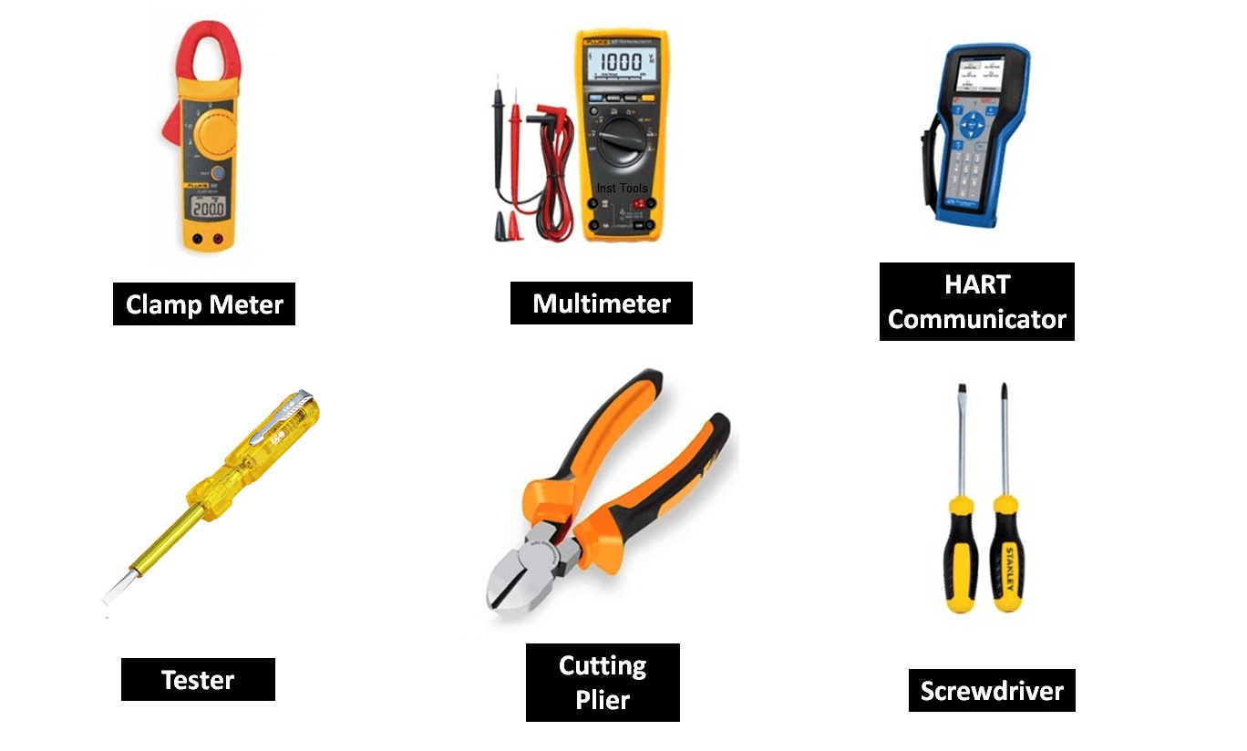
Also Read: Instrument Technician Tools List
Classification of Faults in a PLC System
The Troubleshooting skill does not need a talented person as much as it needs an organized Mindset and very good prepared techniques.
So, you need to categorize and classify the type of faults that you may face:
Hardware Faults
The hardware faults mostly occurred in the field with your physical field devices and it is Caused by:
- Invalid wiring connection of your instruments and control devices.
- Failure in the instrument or in the PLC itself due to many reasons.
Software Faults
The software faults have two main reasons:
- Programming mistakes that is mainly because of some wrong instruction into your code that do not meet the process requirements.
- Software debugs or system errors that may happen if the PLC exceeds the scan cycle time or it can Push your PLC to go in the STOP mode by itself. These faults related to the compiling of your code.
Operator Faults
These types of failures we can call it a non-real fault as there are no any faults except that the operator has no deep understanding of the process, the operator does not know what are the interlocks (made into the programming code) between the machines and each other.
So, he might think that motor A is in a problem but in fact this motor has no any problem and it is only subject to the process conditions.
So, to avoid such a situation you have to understand the whole process very well and relate that to your plant code.
Also Read: DCS System Maintenance
How to Troubleshoot the PLC Hardware Faults?
Troubleshooting is an accurate skill; you cannot imagine how a very tiny wire or device into your Automation system could make a serious fault.
So, if you do not have the experience to notice and expect where is the fault you have to follow these simple procedures:
(by assuming that we have a motor that takes the start order from SCADA but it does not start …)
First of all, you have to ensure that the fault is outside the PLC, by going through the wiring diagram of that motor and get the address of the digital output (DO) that is responsible for energizing the starting relay. As shown in the next two figures:
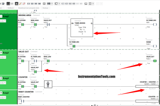
You can see here in Fig (1) that is the wiring of the motor and we have selected it as the relay that is responsible for operating the motor at the AUTO condition.
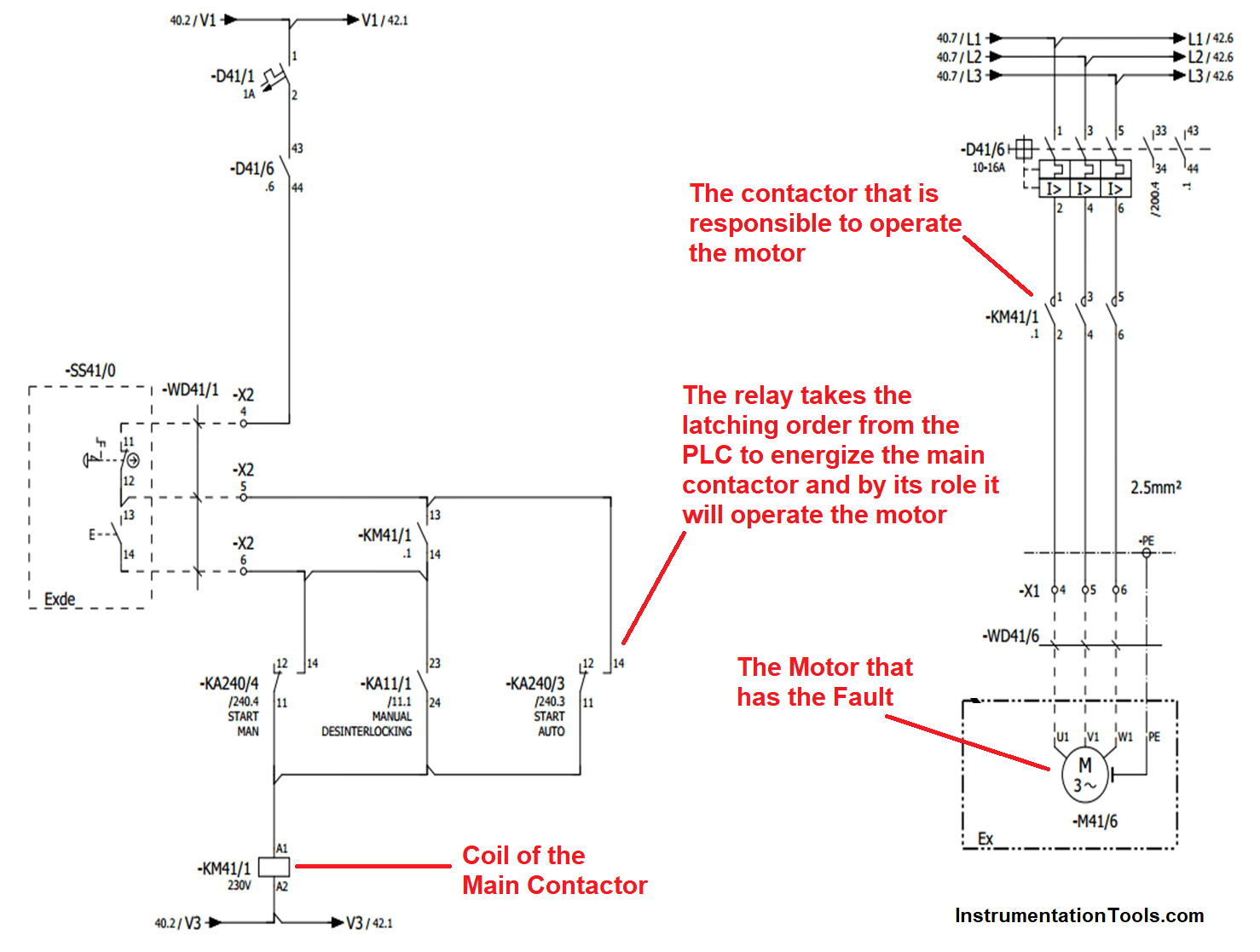
Fig (1)
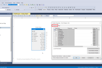
Then you have to search about the Digital output signal that is responsible for energizing that relay (KA240/3) as shown in Fig (2).
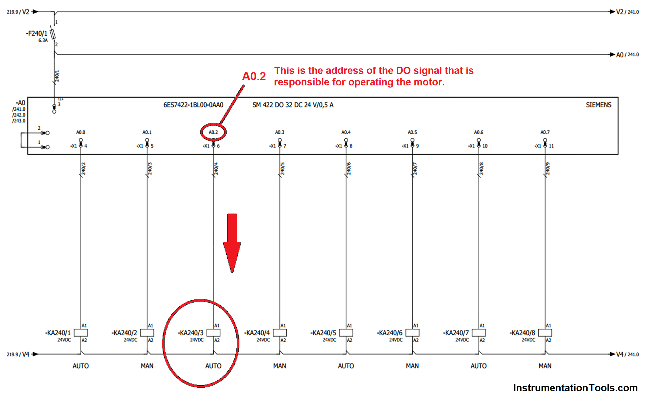
Fig (2)
Now you can go to your PLC card with the Output address and check the output status LED If it is ON that means the PLC is trying to energize the relay but there is a Hardware Fault
If the LED of the output address is OFF that means there is another Software fault inside the PLC.
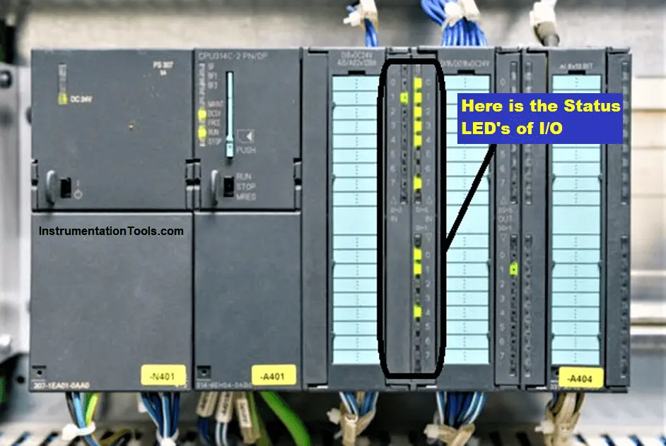
Fig (3)
After limiting the fault in the hardware zone now let us start to track the fault in the Motor circuit.
Most motors in the Automation field consists of two circuits:
- Control Circuit
- Power circuit
So, if you are not experienced to expect where is the fault you have to review each wire and each device at the control & power circuits but that should not be In a random way.
To get the best result you have to track your component with an organized technique (from up to down) or (from down to up).
Power Circuit
Here you can see in the next figure the power circuit diagram for the motor.
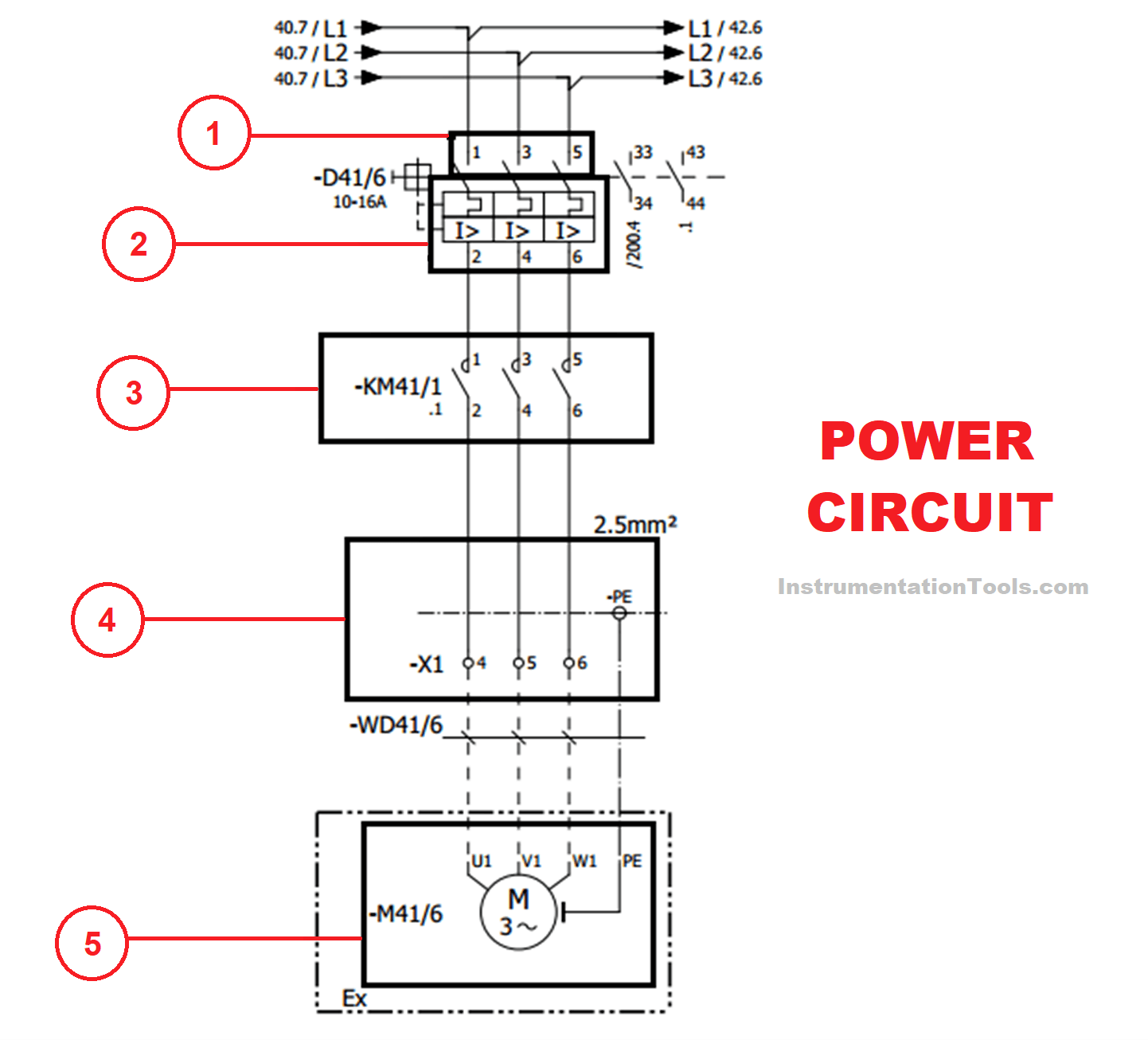
- At the first and by using your Voltmeter you have to ensure that the entry volt between the three phases are healthy (380V).
- Then you need to make the same thing after the circuit breaker (D41/6) to ensure that it is okay.
- To examine the main contactor that operate the motor you have to isolate its connections and try to energize it manually to ensure that all of the three contacts are healthy.
- At the output terminal of the motor control center (MCC) unit you need to check that the power that delivered to the motor are present.
- Finally, and if all of the previous steps are having a good result you have to open the motor itself and make sure that there is no kind of short circuit between the phases and the neutral
Control Circuit
After the fault tracking at the power circuit now we can check the control circuit for the motor.
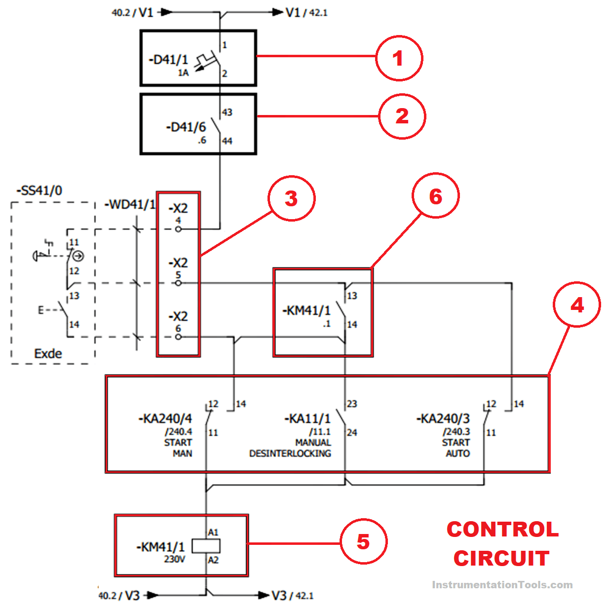
- At first you have to search about (D41/1) circuit breaker and check if it is normally operated and can supply the circuit by 220V
- Then you have to make the same thing for the auxiliary contact that is used from (D41/6) circuit breaker.
- Now you have to check the start stop signal from the field using the buzzer test the terminals (X2-4) & (X2-5) should be short circuit at the normal conditions as that is the stopping push button.
- Then check (X2-5) & (X2-6) as that is connected to the starting push button.
- Here are the relays that are responsible for operating the motor with different methods you have to check the three relays if they are normally operated or not by energizing them manually and check the status of its contacts.
- Here you can check if the coil of the main contactor is healthy or not and make sure that you are suppling the coil with the required power 230V (AC) not 24V (DC).
- Also using the buzzer at the Voltmeter, you have to check the contacts of the contactor if it is normally operating or not, if it is not you can change the contactor by another one.
Summary
As we said before the troubleshooting does not need a talented person as much as it needs a tidy person and also it needs a deep understanding of the Automation control circuit at your plant.
For any other Hardware faults, all you need to do is to make the same procedure at any other control circuit, just determine the begging of the circuit and start to track the fault.
I hope that really would be useful, the next article will talk about the Software faults so stay tuned.
If you liked this article, then please subscribe to our YouTube Channel for Instrumentation, Electrical, PLC, and SCADA video tutorials.
You can also follow us on Facebook and Twitter to receive daily updates.
Read Next:
- Yokogawa DCS Tutorials
- PLC System Cabinet Health Checks
- Communication Protocols in PLC
- User-Defined Function Blocks in PLC
- PLC Interlock Logic with First Input Priority


Respected sir can you please provide an electrical file of any cnc machine in autocad drawing format???