Instrumentation engineering root cause analysis (RCA) of pitot-tube problems and finally replaced with the segment orifice plate.
| Article Type: | Root Cause Analysis (RCA) |
| Category: | Instrumentation |
| Equipment Type: | Transmitters |
| Author: | S. Raghava Chari |
Note: This root cause analysis (RCA) is from real-time scenarios that happened in industries during the tenure of two or three decades ago. These articles will help you to improve your troubleshooting skills and knowledge.
Pitot-tube replaced with Segment Orifice Plate
The cooling water (CW) borne debris and particles plugged the buried 66” cooling water (CW) pipeline Pitot-Tube within 15 days after commissioning the plant CW system and failed the cooling water flow measurements.
The crew pulled out the pitot tube during an opportune entire complex plant shutdown (SD) with great difficulties because flow velocity and turbulence had bent the 2‑m long ¾ pipe PT severely.
The crew straightened as best as possible and the problem repeated within a fortnight. Because of total complex plant shutdown (SD), enormous efforts requirements, and the problems’ too quick repeats, the plant lived with no CW flow measurement.
10-years later a new plant manager insisted on the CW flow measurement, to resolve a doubt whether the CW circulating pumps performing according to their characteristic curves.
Author Solution
The author chose segment orifice and D and D/2 taps because of the below-given reasons:
- Pitot Tube proved unsuitable in this application
- Segment Orifice and D & D/2 offer the below listed advantages:
- It lets all CW borne debris e.g. cooling tower wood fills etc. pass. This way no pipe cross section ‘dam’ does not form and the orifice shown flow readings remain ever accurate
- The permitted liberal tolerances (D/10 upstream and D/20) downstream D and D/2 taps are easy to create and do not choke. Hence, no flow readings interruptions
- Just a 16 mm thick SS plate inserted in the pipe cut slot and welded to the pipeline serves as segment orifice
- Item 3 simplifies the task very much and saves also thus:
- Saves orifice and orifice flange purchase and welding costs; even shops having no lathes can make it
- The flow meter starts working 6-months sooner, the flanges delivery time
- Less depth and sides excavation to insert the orifice, less flame cutting and welding and hence less lining damage, less lining repair costs and less backfill costs
- Most important: job completion feasibility during the 2-months hence scheduled TA
- Around Rs 200000 saved costs
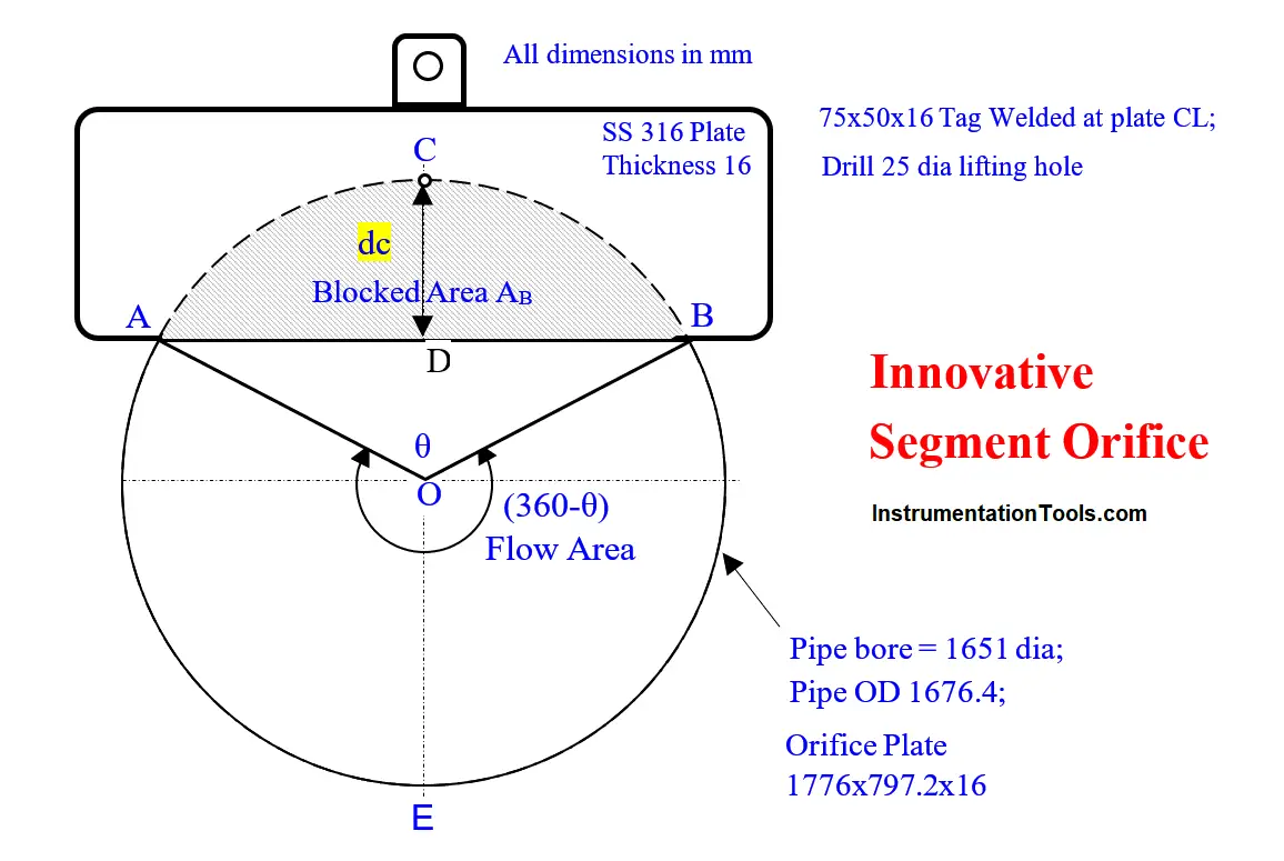
Orifice Sizing Constraint Resolved
The instrument engineer assigned to size the orifice an hour later sheepishly grinning approached the author, showed his below-given calculations:
| Stuck Segment Orifice Sizing Step Unstuck | |
| Pipe Bore dia mm | 1651 |
| Pipe Bore Area APB =0.25*Pi()*1651^2 | 2140839 |
| Flow Area Af 0.57*APB | 1220278 |
| Af sector suspended angle – see fig | (360-θ) |
| Af =(360-θ)*APB/360 + 0.125*1651^2*SIN(RADIANS(θ)) | |
| While iterating at θ = 167.35 Af | 1220263 |
| Convergence – really close convergence! | -15 |
| Hence let us accept it and calculate chord distance dc from pipe bore top; dc =0.5*1651*(1-COS(RADIANS(0.5*167.35))) = 734.6 mm | |
| Hence, Plate length = 1651+2* pipe wall thickness 12.5+ projection from pipe OD 2*25 = 1651+2*12.5+2*25 | 1726 |
| Plate Width = 734.6+12.5+25= | 772.1 |
and said, “Sir, step 6 for Af calculation from the fig involves both θ and Sin θ. I am stuck there. Please unstick me. I consulted a couple of our and technical department colleagues; they are unable to help out!
The author thought for a while and said, from the drawing θ looks approx. 160o. Just iterating the equation around this angle in an excel sheet will get you θ’s value and enable sizing the plate. The engineer thanked the author and sized the plate as the table shows.
The workshop readied the plate and scribed the pipe OD symmetrically and 25 mm away from the plate top. In addition, they welded 100 mm long Sch 160 nipple to a ¾” x 6000 psi socket and another same assembly.
A contractor excavated a 1000 x 1000 mm area at an orifice location up to ½ the pipe dia. The contractor grouted a 2 m long pipe pillar at the instrument mechanic shown point near the orifice.
The instrument crew mounted a DPT calibrated to the sized DP on the pillar. During the turnaround (TA) pipe crew installed the orifice as the instrument technician showed and the welder welded the orifice to the pipe cut slot.
The instrument crew connected the process leads and supply air and signal air tubes to the DPT and readied the flow meter.
Benefits Realized
The reliable flow meter readings proved the pump delivering the correct quantities and prompted more detailed studies which pin pointed the large steam turbines’ surface condensers and other heat exchangers water circuits’ so much fouling that one wondered how water ever flowed as the root cause of absurd process streams temp readings and the resultant far below rated capacity production allover.
Resolving these problems increased plant production 10% more than rated capacities and averted the proposed Rs 20 million costing CW pump purchase.
Author: S. Raghava Chari
Do you face any similar issues? Share with us through the below comments section.
If you liked this article, then please subscribe to our YouTube Channel for Instrumentation, Electrical, PLC, and SCADA video tutorials.
You can also follow us on Facebook and Twitter to receive daily updates.
Read Next:
- Actuator Diaphragm Bursts
- Control Valves Leak Tightness
- Over-Capacity Control Valve
- Control Valve Gland Leaks
- Transmitter Pressure Correction


Thank you sir for sharing your valuable experiences with us.
Hope you plan using it; what attracted you to this most out of the numerous other solved problems
Sir, we have a problem with flowmeters in a process. The flow meters readings are not matching with each other. After doing some troubleshooting, we find out that the DP generating from each orifice are different and so the difference in flow measurement.
Some orifice plates specifications are wrongly selected and this is the reason. We found the reason after many months and during a unplanned process plant shutdown. I understand different reasons and causes of instrument problems from your articles. We may or may not have these problems but learning them is definetly an advantage. Thank you.
Karim,
Below are the reasons for orifice flow meter readings differences
1. Different Vendors supply different plant sections; usually slight differences in flow conditions data e.g., pressure, temp and density each vendor assumed often slightly differ.
2. A major difference producer is pipe ID; take a 20” Sch 40 pipe. Its nominal OD – 508 mm OD tol is +/- 1% and thickness 15.09 mm, tol +/- 12.5%; take it as 16 mm for easy calculations.
3. Vendor A got pipe OD could be 508+5= 513 mm and wall thickness 14 mm; hence ID = 513-2*14= 485 – extreme case
4. Vendor B got pipe OD could be 508-5= 503 mm and wall thickness 18 mm; hence ID = 503-2*18= 467 – extreme case
5. Orifice designer uses the nominal pipe ID = 508-2*16= 476 mm
6. The flow meter error is proportional to ID^2; Vendor A’s flow meter error =-100*(1-467^2/476^2) = -3.75%.
7. Similarly vendor B’s flow meter error at the same orifice ΔP=100*(1-465^2/476^2) =4.57%.
8. The difference between the two flow meter readings =4.57-(-3.75) = 8.32%.
9. However the two flow meters readings are reproducible
10. Hence, the plants use orifice flow meters for plant operation and control only and for custody transfer i.e., sale to others users turbine, Corioliss flow meters or radar level gauges measured certified tank levels only.
11. One way to narrow the differences between orifice flow meters at different locations is to use the actual pipe IDs at orifice locations: Micrometer Measure the pipe OD and wall thickness with a calibrated ultrasonic thickness gauge and calculate the pipe ID instead of using the nominal pipe ID
I hope this explanation satisfies you.
Raghava Chari
Thank you sir for detailed information on orifice.
very helpful.