Inst ToolsInst ToolsInst Tools
  • Courses
  • Automation
    • PLC
    • Control System
    • Safety System
    • Communication
    • Fire & Gas System
  • Instrumentation
    • Design
    • Pressure
    • Temperature
    • Flow
    • Level
    • Vibration
    • Analyzer
    • Control Valve
    • Switch
    • Calibration
    • Erection & Commissioning
  • Interview
    • Instrumentation
    • Electrical
    • Electronics
    • Practical
  • Q&A
    • Instrumentation
    • Control System
    • Electrical
    • Electronics
    • Analog Electronics
    • Digital Electronics
    • Power Electronics
    • Microprocessor
  • Request
Search
  • Books
  • Software
  • Projects
  • Process
  • Tools
  • Basics
  • Formula
  • Power Plant
  • Root Cause Analysis
  • Electrical Basics
  • Animation
  • Standards
  • 4-20 mA Course
  • Siemens PLC Course
Reading: Electrical Symbols
Share
Notification Show More
Font ResizerAa
Inst ToolsInst Tools
Font ResizerAa
  • Courses
  • Design
  • PLC
  • Interview
  • Control System
Search
  • Courses
  • Automation
    • PLC
    • Control System
    • Safety System
    • Communication
    • Fire & Gas System
  • Instrumentation
    • Design
    • Pressure
    • Temperature
    • Flow
    • Level
    • Vibration
    • Analyzer
    • Control Valve
    • Switch
    • Calibration
    • Erection & Commissioning
  • Interview
    • Instrumentation
    • Electrical
    • Electronics
    • Practical
  • Q&A
    • Instrumentation
    • Control System
    • Electrical
    • Electronics
    • Analog Electronics
    • Digital Electronics
    • Power Electronics
    • Microprocessor
  • Request
Follow US
All rights reserved. Reproduction in whole or in part without written permission is prohibited.
Inst Tools > Blog > Electrical Theory > Electrical Symbols

Electrical Symbols

Last updated: July 22, 2018 9:03 pm
Editorial Staff
Electrical Theory
No Comments
Share
0 Min Read
SHARE

To read and interpret electrical system diagrams and schematics, one must be thoroughly familiar with the many symbols used. Once these symbols are mastered, most electrical diagrams and schematics will be understood with relative ease.

The symbols for the various electrical components that will appear on electrical diagrams and schematics are shown in Figure 30.

Electrical Symbols

Electrical Symbols

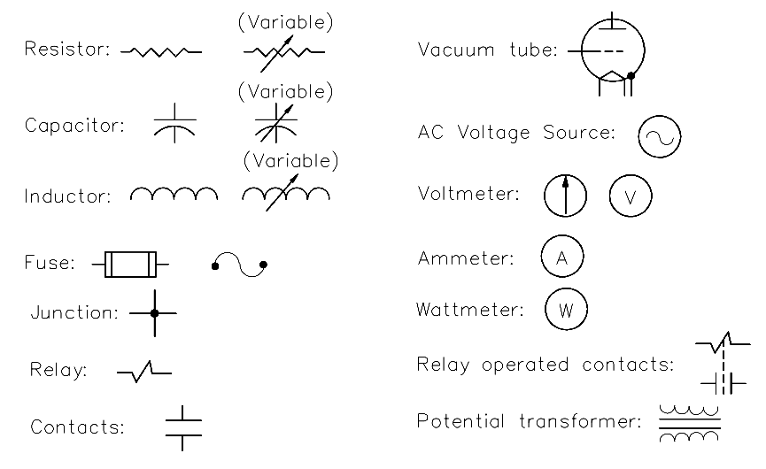
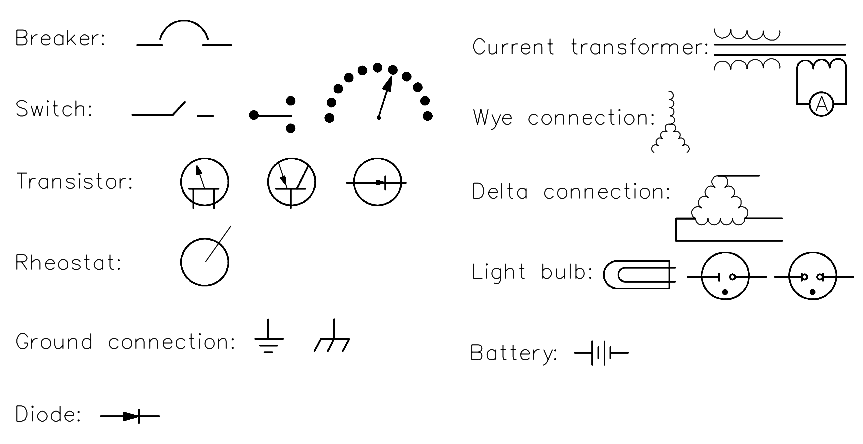
Figure 30 Electrical Symbols

Don't Miss Our Updates
Be the first to get exclusive content straight to your email.
We promise not to spam you. You can unsubscribe at any time.
Invalid email address
You've successfully subscribed !

Continue Reading

AC Generator Voltage Regulators
Full-Wave Rectifier Circuit
Wiring Diagram
Series Circuit
Transformer Mutual Induction
DC Motor Theory
Share This Article
Facebook Whatsapp Whatsapp LinkedIn Copy Link
Share
Leave a Comment

Leave a Reply Cancel reply

Your email address will not be published. Required fields are marked *

Stay Connected

128.3kFollowersLike
69.1kFollowersFollow
210kSubscribersSubscribe
38kFollowersFollow

Categories

Explore More

Kirchhoff’s Laws
Battery Operation : Series and Parallel
Applying Kirchhoff’s Voltage Law
DC Generator Internal Losses
Compound Generators
Block Diagram
Transformer Theory of Operation
Transformer Operation Under No-Load

Keep Learning

Power Triangle

Apparent Power, True Power, Reactive Power & Total Power

Thermoelectricity principle

Methods of Producing Voltage (Electricity)

Current Law

Applying Kirchhoff’s Current Law

Leading Power Factor

Power Factor

Phase angle

AC Generation Analysis : Effective Values, Phase Angle and Frequency

Three Phase Transformer Connections

Three Phase Transformer Connections

Series-Wound DC Generator Principle

Series-Wound DC Generators

Lead Acid Battery charge

Discharge and Charging of Lead-Acid Battery

Learn More

Comparator used in Siemens S7-1200 PLC.

Siemens PLC Comparator Logic

Electrical Machines Questions and Answers

Autotransformers

Impulse Line Problems

What are Impulse Lines? – Impulse Line Problems & Solutions

How to test SCR using Multimeter

How to test SCR using Multimeter

How to Select Right Thermocouple and Thermowell

How to Select Right Thermocouple & Thermowell ?

Look Listen Feel of Instruments

Look Listen Feel of Instruments – Instrumentation Engineer Maintenance

Power Systems Questions & Answers

Power Systems MCQ Series 6

Best Practices of PLC Wiring

Best Practices of PLC Wiring – Programmable Logic Controller

Menu

  • About
  • Privacy Policy
  • Copyright

Quick Links

  • Learn PLC
  • Helping Hand
  • Part Time Job

YouTube Subscribe

Follow US
All rights reserved. Reproduction in whole or in part without written permission is prohibited.
Welcome Back!

Sign in to your account

Username or Email Address
Password

Lost your password?