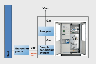
Instrumentation engineering root cause analysis (RCA) of flow transmitter pressure-temperature correction factors in pneumatic instrumentation.
| Article Type: | Root Cause Analysis (RCA) |
| Category: | Instrumentation |
| Equipment Type: | Transmitters |
| Author: | S. Raghava Chari |
Note: This root cause analysis (RCA) is from real-time scenarios that happened in industries during the tenure of two or three decades ago. These articles will help you to improve your troubleshooting skills and knowledge.
Problem
The process licensor has forgotten to order and hence not available temperature transmitters threatened 6-months total plant commissioning delay – their rush order delivery time.
Author solution
The author recommended omitting the temperature correction attributing the below-given reasons:
Gas flow temperature correction is usually very small.
Example: correction factor at 50o C gas temperature for orifice design 40o C is just
=1-((273+40)/(273+50))^0.5 = 1.56 % only.
But calibrating pneumatic temperature transmitters for the required 0 to (273+60) K is very hard as sub-zero temperature baths are usually not available in most plants instrument workshops, hard to get.
Hence, flow temperature correction using pneumatic temperature transmitters introduces significant errors instead of refining the readings.
The plant where the author worked asked the author to remove both; however, they retained pressure correction only as the problems are absent with even pneumatic transmitters correction factors are significant.
The management accepted the recommendations and asked the author to configure the system for pressure correction only.
Also Read Theory: Flow Meter Pressure Temperature Correction
Gas Flow Meter Pressure Correction
The pressure correction equation is
QNC = QNR (hPA /PD)0.5 ; Equation 1; Symbols explanation follow.
QNC is Correct flow rate in Nm3/H =KhC0.5
QNR is Flow meter reading in Nm3/H =KhR0.5
KhC0.5= KhR0.5*(PA /PD)0.5 Cancelling K we get
hC0.5= hR0.5*(PA /PD)0.5
K is The flow installation constant
h is the Differential pressure across the orifice
Pd is the Orifice design assumed pressure Kg/Cm2 abs.
Pa is the Actual Pressure Kg/Cm2 abs
Pressure Correction Pneumatic Instrumentation
The available analog computer’s one possible configuration is calculating hC0.5=(h*Pa)0.5 offering the advantages of flow correction for pressure variations from orifice design pressure and 0‑100% easier to read flow receiver linear scale.
In addition, it eliminates the vendor given linearizing additional analog computers.
QNC=(h*Pa/PD)0.5. (1/PD)0.5 is a constant.
Hence include it as a second instrument scale factor.
The below given example illustrates it.
Example: Orifice Design Data as follows
Q= 40000 Nm3/H;
PD=7 Kg/Cm2 abs
h=2500 mm WC.
K=40000/25000.5 = 800.
What is the correct reading when the receiver shows as follows
32000 Nm3/H and PA=7.5 Kg/Cm2 g?
h0.5=32000/800=40; h=1600 mm WC
Instrument Calibrations
DPT 0-2500 mm WC and PT 0-10 Kg/Cm2 abs;
DPT output Signal Fraction (SF)= 1600/2500 = 0.64
PT output SF=(7.5+1.03)/10= 1.03 added to get abs pressure 0.853
Hence analog computer output SF = (0.64*0.853)0.5 = 0.739
PD SF=(7+1.03)/10 = 0.803
Hence 2nd Scale Factor c = (1/0.803)^0.5 = 1.116
Hence QNC=1.116*0.739*40000;
as SF 1=40000 Nm3/H = 32988
% correction’n =100*(32988-32000)/32000 = 3.09%
Do Manual =((7.5+1.03)/(7+1.03))^0.5 -1 = 3.06%
Both tally.
Author RCA Solution Benefits
Below given are the Author RCA benefits:
- Min 6 months commissioning delays gone
- Absence of temperature correction avoids future recurring problems and even plant shutdowns leading to its eventual removal
- No wasteful TT purchase and installation expenses and subsequent removal after facing operation inconveniences
- 4 spared analog computers, which can be configured for other instruments’ pressure correction tasks when needed.
Author: S. Raghava Chari
Do you face any similar issues? Share with us through the below comments section.
If you liked this article, then please subscribe to our YouTube Channel for Instrumentation, Electrical, PLC, and SCADA video tutorials.
You can also follow us on Facebook and Twitter to receive daily updates.
Read Next:
- Actuator Diaphragm Bursts
- Control Valves Leak Tightness
- Over-Capacity Control Valve
- Control Valve Gland Leaks
- DP Transmitter Stopped Working