In this article, we will talk about closed-loop control systems, manual control, and ON-OFF with hysteresis and we will show a PLC simulation for each type.
Contents:
- What is manual control?
- What is closed-loop control?
- Why do we need closed-loop control?
- What are the different types of closed-loop control?
- ON/OFF control
- ON/OFF control with Hysteresis.
- System simulation.
- System description.
- Simulating the behavior of the tank and level sensor.
- Manual mode programming.
- ON/OFF Control.
- ON/OFF control with Hysteresis.
- Simulation of the system.
What is Manual Control?
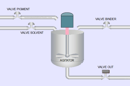
To understand what manual control is, imagine that you have a tank filled with water, this tank feeds water to a 5 apartments building, the demand from this tank will probably be continuous and also variable depending on the apartment’s different needs. Now imagine having to manually control the tank so it would always be filled at 80% of the maximum level. You would manually control the start/stop of a pump assuming a constant flow pump or you would control the ON/OFF of a water supply valve.
To manually control the level and keep it at 80% wouldn’t be easy, because you will have to adjust the frequency of the pump running and stopping or the degree of opening of the valve depending on the demand from the apartments, and as the demand is variable, keeping the level at the 80% won’t be possible.
Manual control doesn’t have any feedback signals, so you need to observe the tank level by yourself and decide when to run or stop the pump. See the following simulation of the manual control system.
As you can see from the simulation, there is no feedback signal for the tank level, you have to observe it by yourself and then decide to run or stop the pump. You will also notice that it is hard to keep the level at a certain point because the demand is variable and changes all the time.
What is a Closed-loop Control?
A closed control system is a system that will continuously monitor your process parameters (in our case the level of the tank) and decide when to supply water to the tank and when to cut off the water supply.
For a closed loop control you would need some elements in your system, these elements are:
- Sensing element to monitor the water level.
- A control element to take action on whether to supply water on not.
- Actuator elements like a pump or a valve to supply water to the tank.
Why do we need closed-loop control?
With a closed loop system, you always have feedback on your process parameters which allows the controller to act more quickly and accurately to these changes.
With a feedback signal of your process parameters, you can detect any faults or abnormal behavior of your process, which gives you a more safe and reliable system.
Overall, closed-loop control systems provide greater control, stability, and adaptability compared to open-loop systems, making them a preferred choice in a wide range of applications where accuracy and performance are critical.
What are the different types of closed-loop control?
There are many types of closed loop systems, but most commonly used are three types of closed loop control and in this article we will discuss two and the third type will be discussed in another article.
Closed loop control types:
- On/OFF control.
- ON/OFF control with Hysteresis.
- PID control.
ON/OFF Control
In this type of control, the controller will turn on the pump immediately when the tank level exceeds the set point and it will turn off the pump immediately when the tank level drops below the set point.
But, you should know that this behavior is not very healthy for your pump as it might run/stop with a high frequency putting the pump under a lot of heavy work which might cause it to burn out.
Plus, in ON/OFF control you don’t really have control over the pump flow, it is either on with full power or completely off. This will make it very hard for the controller to keep the level of the tank at the needed set point. As we will see in the simulation.
ON/OFF control with Hysteresis
The “ON/OFF control with Hysteres” is exactly the same as the ON/OFF control, but with an added tolerance to the set point, meaning the level of the tank is not allowed to be within a certain tolerance of the set point. To help the pump run more smoothly and prevent frequent start/stop of the pump to protect it from burning out.
However, this control will depend on the behavior of the pump whether is it working with different flows or it is just on-off the pump. If the flow of the pump is controlled then the behavior will be better, but if it just on-off of the pump, then it will be like the previous control but with a longer running time of the pump. we will see in the simulation.
- System simulation.
- System description.
- Simulating level sensor and the pump.
- Manual mode programming.
- ON/OFF Control programming.
- ON/OFF control with Hysteresis programming.
- Simulation of the system.
System Simulation (system description)
imagine that you have a tank filled with water, this tank feeds water to a 5 apartments building, the demand from this tank will probably be continuous and also variable depending on the apartment’s different needs. The tank capacity is 50 liters, and we need to control the tank level to be at 30 liters or any other set point that we choose.
For this system, we will need a level sensor and a pump. We will assume an analog level sensor that gives a 0-10v signal and a 0-10 liters/sec pump that is controlled via a 0-10 volts output signal.
As we don’t have an actual pump or actual sensor, we will simulate their behavior in our PLC.
Simulating Level Sensor and the Pump
A level sensor will convert the 0-50 liters level of the tank into a 0-10v signal which then goes into the PLC analog input module.
The 0-10v readings at the analog input will be converted back to the 0-50 liters level of the tank. See picture 1.
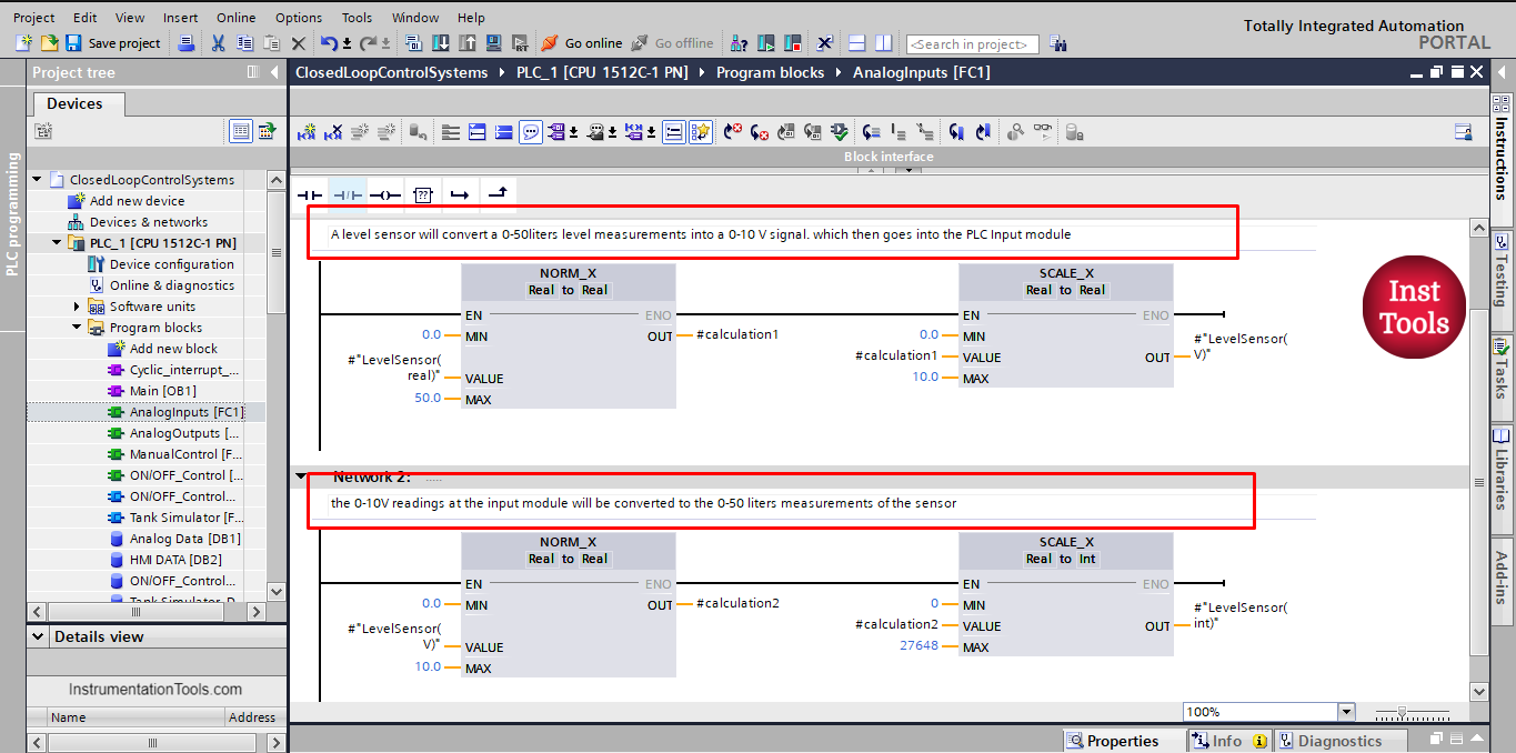
picture 1. Simulating the level sensor.
For the pump, the PLC output module will take the output value 0-32767 from the program calculation and turn it into the 0-10v output signal.
The pump will then take the 0-10v signal range and convert it to the 0-10 liters/sec pump flow. See picture 2.
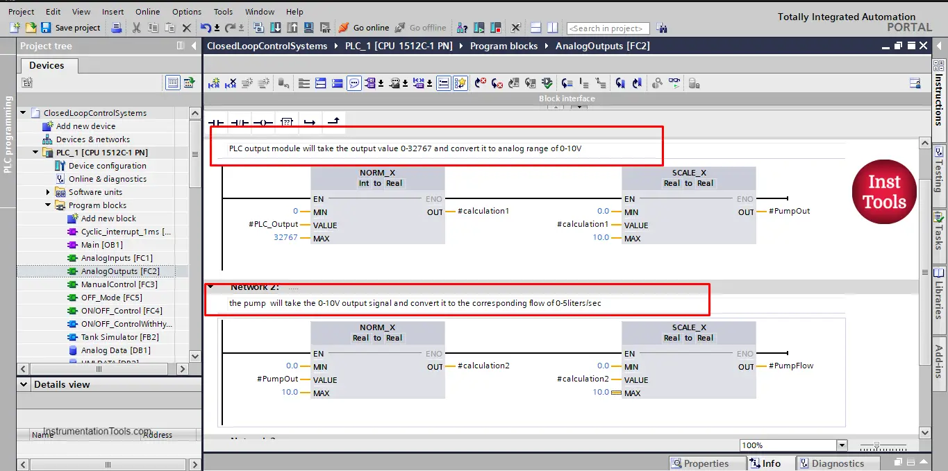
Picture 2. Simulating the pump output.
Manual Mode Programming
For manual mode, we don’t have any feedback signal, so the level sensor is not used, you just have manual control over the start/stop of the pump. See picture 3.
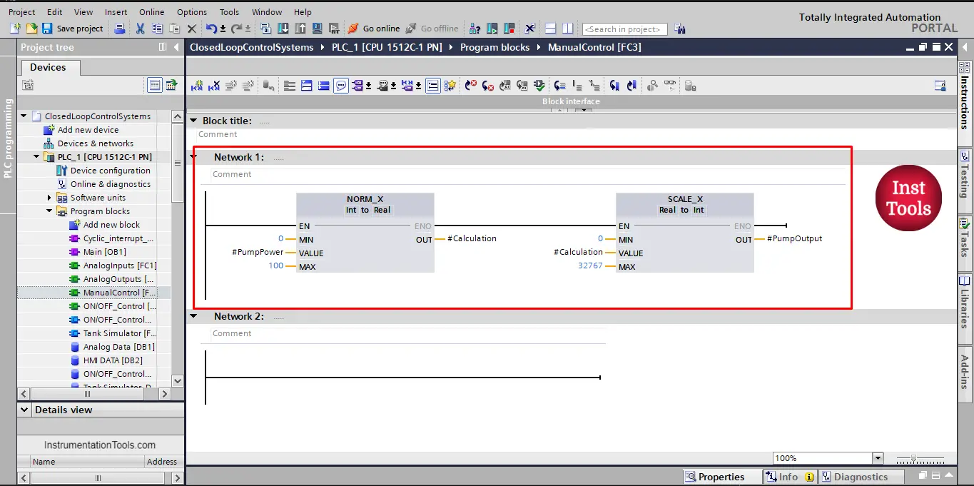
picture 3. Manual control mode.
As you can see, a #PumpPower signal will control the pump, this signal will come from the HMI.
ON/OFF Control Programming
In this mode, a set point will control the start/stop of the pump. See picture 4.
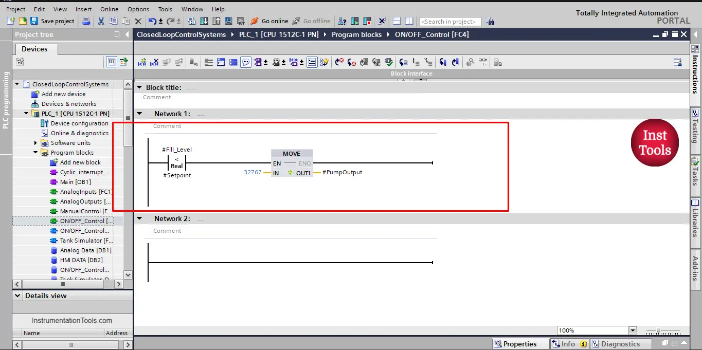
Picture 4. On/off control.
As you can see, whenever the #FillLevel is below the #SetPoint the pump will immediately run at full power. And it will stop immediately when #FillLevel equals the #SetPoint. We will see in the simulation the effect of that behavior.
ON/OFF Control with Hysteresis Programming
In this mode, there will be an upper limit and a lower limit to control the run/stop of the pump. See pictures 5 and 6.
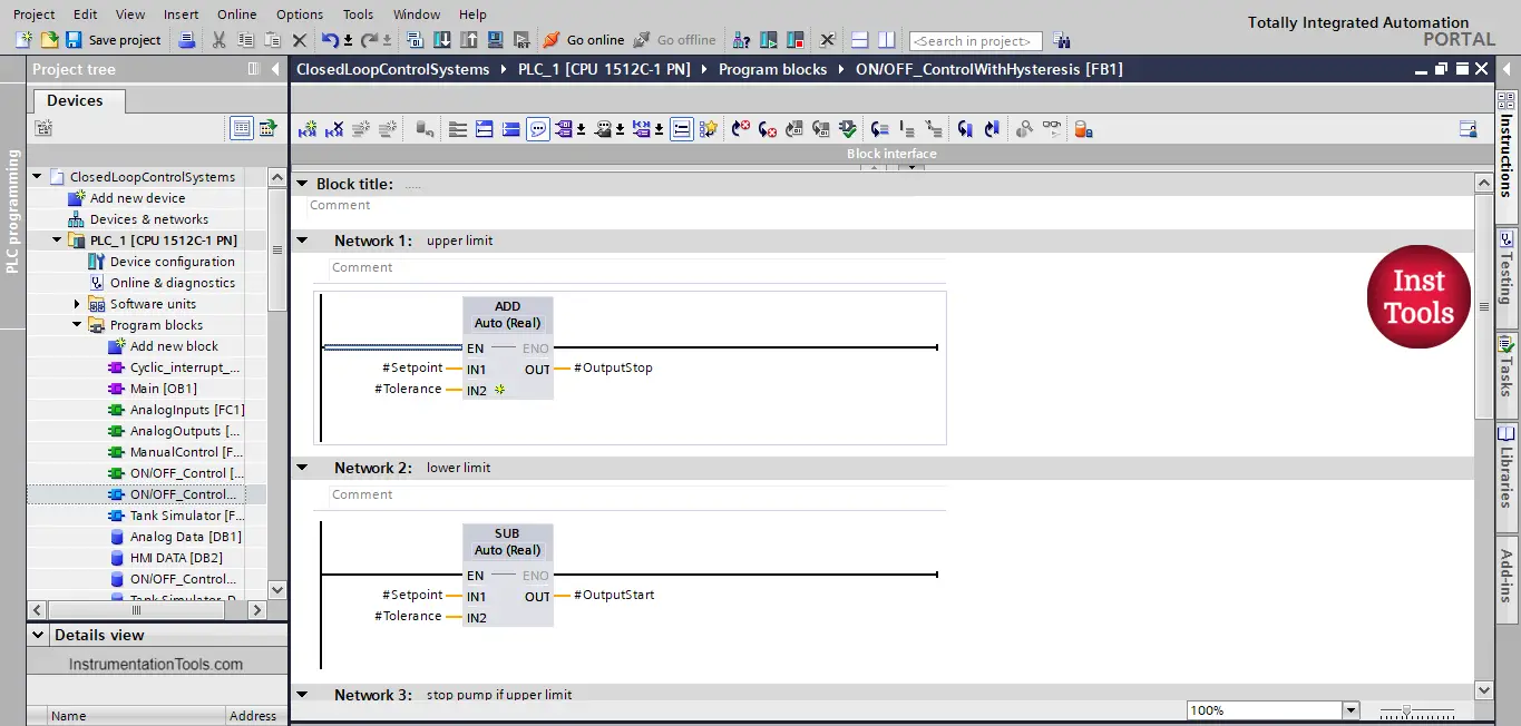
picture 5. The upper and lower limit of the set point tolerance.
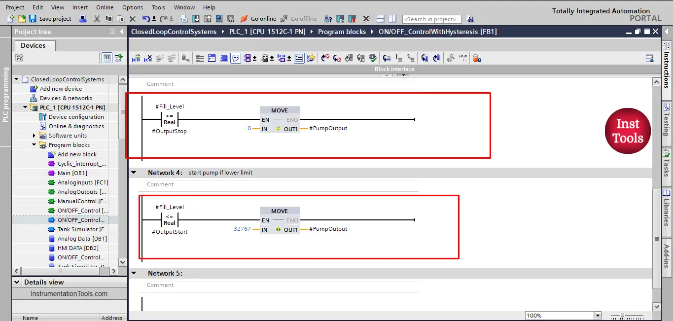
picture 6. On/off control with tolerance.
Now, we will call our functions into our main OB1, see picture 7.
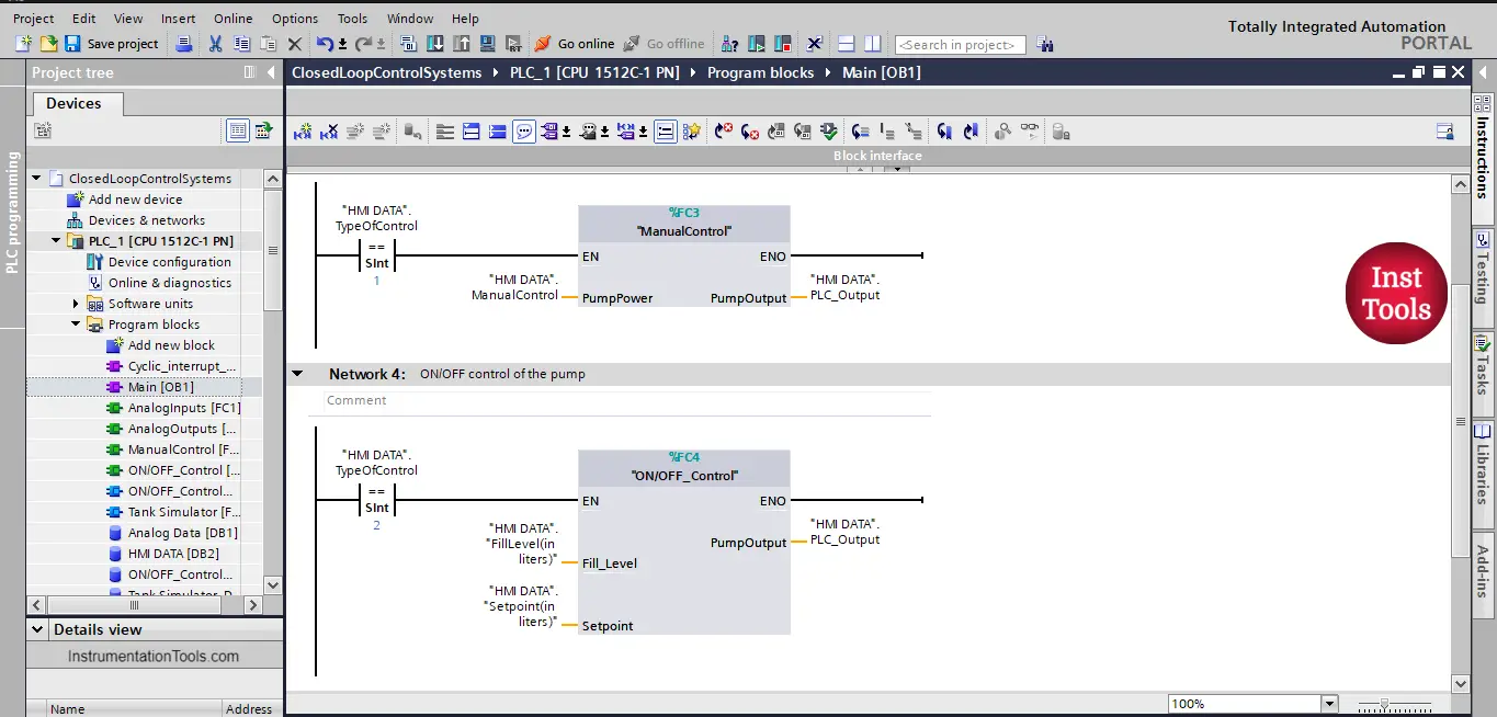
picture 7. Calling our functions in OB1.
PLC Simulation of the System
To simulate the system, we have created a simple HMI simulation and defined the needed parameters to show how the different control type will work. We need to understand some parameters we have created to make the simulation as real as possible. There is a function block FB called tank simulator, that was created to give the system a real-like behavior, you don’t need to understand completely how it works, but you can open up the function and read through its code.
However, some parameters you need to understand, and they are the following:
Idle time:
Any real pump will take some milliseconds before it can reach its full power or any other flow power, it doesn’t immediately jump to full power. This was included in the simulation to give a real behavior of the pump.
Outflow:
This is the demand of your system, it is set to be a % of the level of the tank. In the simulation, we manually write the outflow.
Disturbance:
A real system will have some kind of noise or random disturbance that can affect the behavior of the system, this was also included in the simulation.
Check the following simulation video to see how the system behaves with different controller types.
In the video, you can notice that, when the system type is ON/OFF the pump is starting and stopping a lot of time in a short period of time. Which might cause the pump to burn out.
When a tolerance is provided, the pump will have a fewer start/stop time and a relatively longer running time.
In both control systems, you can see that maintaining the tank level at the set point is not achieved all the time, because the outflow can change at any time and also the random disturbance.
A better type of control that will have a smooth operation of the pump and also maintain the tank level at the needed set point almost all the time is the PID controller type, which we will discuss in another article.
You can now download the simulation program and experiment yourself with the different behavior of the system with different conditions of outflow, idle time, and random disturbance.
Conclusion
- Manual control or open-loop control doesn’t have a feedback signal.
- The closed-loop system will have a feedback signal to monitor your process parameters.
- There are many control types of closed-loop signal like on/off and hysteresis control.
- Each type of control will behave differently with the changes in the process parameters.
- Maintaining a constant level with the on/off or hysteresis control is hardly achieved if the outflow and the disturbances are changing all the time.
If you liked this article, then please subscribe to our YouTube Channel for Instrumentation, Electrical, PLC, and SCADA video tutorials.
You can also follow us on Facebook and Twitter to receive daily updates.
Read Next:
- HMI Screen Design Applications
- Static and Temp Variables in PLC
- Power Supply Sizing for Systems
- How to Read the PLC Datasheet?
- Firmware Version of a PLC System