In a previous article, we talked about what a PID is, and we also explained the different parameters of a PID and how the system would react to changing these parameters. In this article, we will show how to program, configure and tune a PID in your TIA Portal project.
Contents:
- How to add a PID to your logic?
- How to configure the PID?
- Basic setting process value setting
- Advanced setting
- How to perform tuning of the PID?
- Pre-tuning of the PID
- Fine-tuning
- What are the different tuning methods of PIDs?
How to add a PID to your logic?
In TIA Portal and almost every other PLC platform, you don’t have to program a PID controller as the TIA Portal already has built-in blocks for PIDs. To add a PID into your logic you just have to simply drag and drop the PID block into your code and just start configuring it for your system.
Adding PID into your code is very simple, however, there is a very important point you should take into your consideration. This is the execution interval of your PID.
As you know the main execution cycle is happening inside Main Cyclic OB1 and the cycle time of the OB1 depends on a lot of factors, like how long your code is, mathematical calculations in your code, and also for loops and sequences, all of these different factor would make the cycle time of your OB1 not only might it make it long but also it will make it different each cycle, depending on the coding you have.
That means if you called your PID block inside the main OB1, the PID execution will depend on the cycle time of your OB1, and that is not a best practice approach.
PIDs are usually used to control physical parameters like pressures, temperatures, or speeds and that means your controller needs to be very fast in figuring out any change in your process value and taking fast reactions to counter-effect this change and give you a smooth stable control that a PID should have. So if the PID is added to the main OB1 and is affected by its execution time, it might need to action delays and it will make your system not stable.
What to do?
A best practice is to call your PID block in a cyclic interrupt OB and set the cycle time of this cyclic interrupt to whatever value you see fit for your system, usually in the range of milliseconds depending on your application. That means, if you set the cyclic interrupt for example to 1 millisecond your PID will be called and executed every millisecond regardless of where the main OB1 cycle is.
So, to add a PID into your logic we start by adding a new cyclic interrupt OB and give it a proper name. See picture 1.
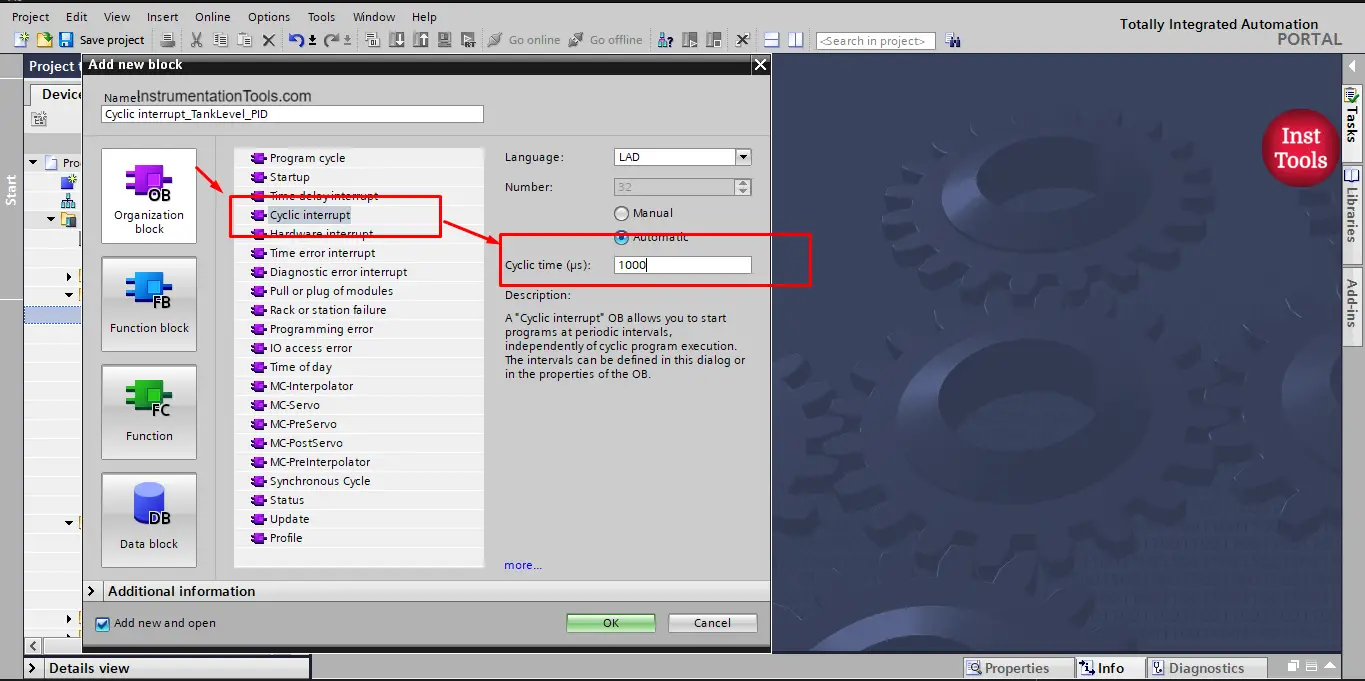
Picture 1. Adding a cyclic interrupt into your project.
You can see from the picture that we set the cyclic time to 1000 microseconds or 1 milliseconds. So our PID will be called and executed every millisecond.
Now that you added your cyclic OB to the project, you can simply drag and drop the PID block. You can find it in the Instructions tab/Technology/PID control/Compact PID. See picture 2.
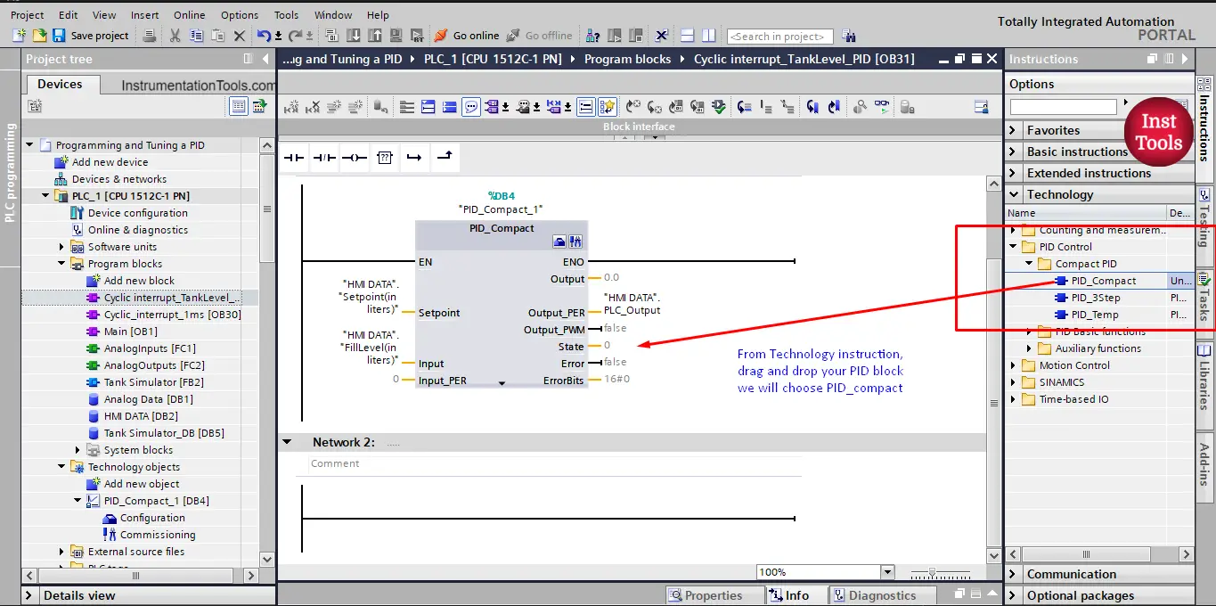
Picture 2. Adding the PID block.
Now, add your system parameters to the PID block, the input, output, and setpoint. See picture 3.
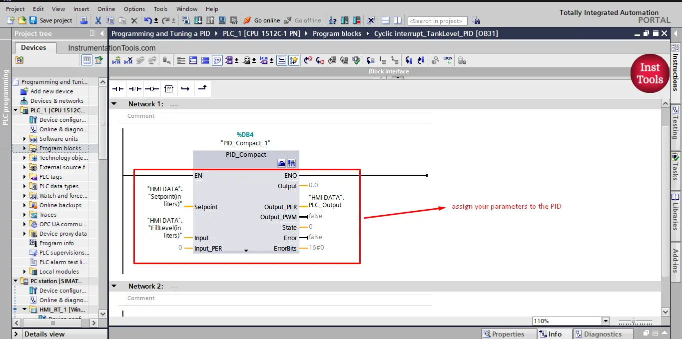
Picture 3. Assign your PID parameters.
Did you notice from the last picture, you have 2 different inputs and 3 different outputs, what are those?
Input:
This is your input value of your process parameter in real actual physical quantities, we will use our tank simulation system, so the input here in that case is the tank fill level in liters. That means you have made your analog input scaling somewhere else in your project and you just supply the PID with the actual fill level in liters.
Input_PER:
This is the input value of your process parameter but comes from the analog input module. That means it will not be scaled and it will be in the range of 0-27648 and the scaling of the input will be done inside the PID.
Output:
In this case, the PID will give you the controller output value in the range of 0% to 100% of the maximum output value.
Output_PER:
The same as input_PER, the PID will give the output in the form of 0-27648.
Output_PWM:
In this case, the PID will give its output signal in the form of ON/OFF pulses, so either there is an output or not. And the output value is then 100% when it is ON and 0% when it is OFF.
We will use the same tank simulation system we used before, and as you can see from the previous picture, we used the Input and Output_PER as our simulation is built this way.
How to configure the PID?
To enter the configuration view of the PID, you can either click the configuration tab in the project tree or from the small configuration icon above the PID block itself. See picture 4.
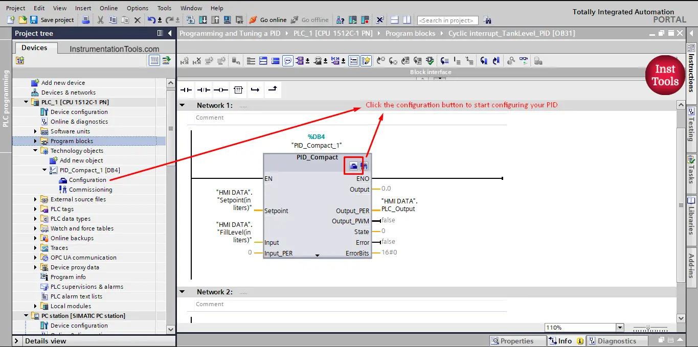
Picture 4. Entering configuration view.
This will take you to the functional view where you can configure the different settings of your PID. See picture 5.
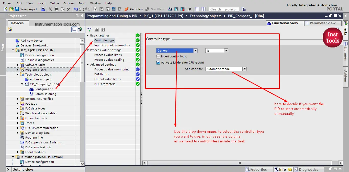
Picture 5. Controller type setting.
The first configuration is the controller type, and here you can choose what type of control you want to use, you have a lot of options from the shown drop-down menus like temperature, pressure, length, and many more. You can also set it to general, where the system will see your values as %. In our system, we are controlling water liters inside a tank, so we will choose volume.
You can also set the Manual/Auto mode of the PID.
Next, you want to configure the input/output parameters. See picture 6.
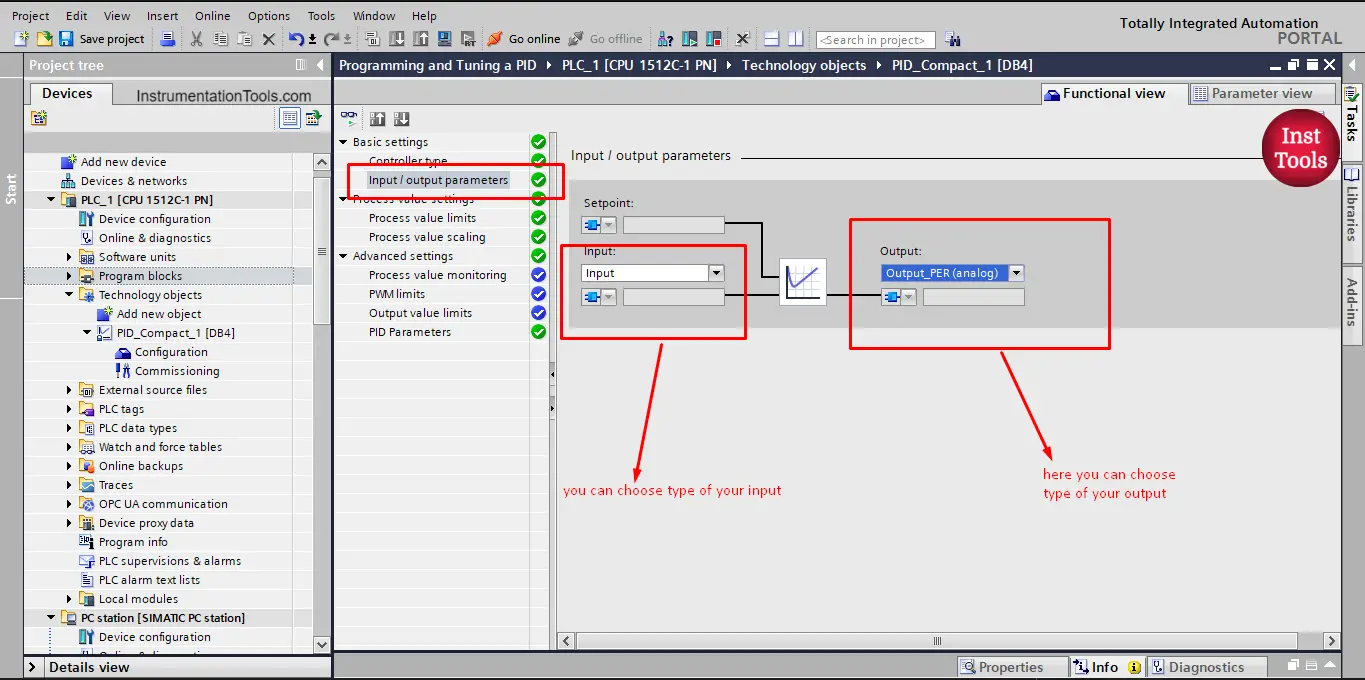
Picture 6. Input/output parameters.
Here you can choose from the different types of inputs or outputs as we explained before. As we said we will use the Input and Output_PER.
Next, you need to configure your process value setting. See picture 7.
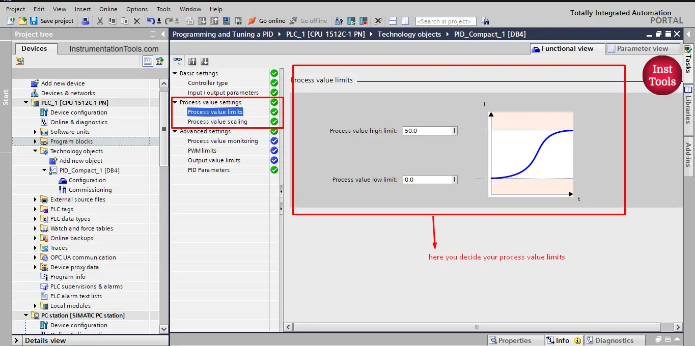
Picture 7. Process value limit.
In this step, you will set the low and high limits of your process value. If you choose the Input type. Then this setting will be open to change, and you can set the limits of your process. In our case, the tank limits are 0 to 50 liters. So we set it to these values.
Note that, if you choose the Input_PER this setting won’t be available to you and you can only set your process limit from the next tab. See picture 8.
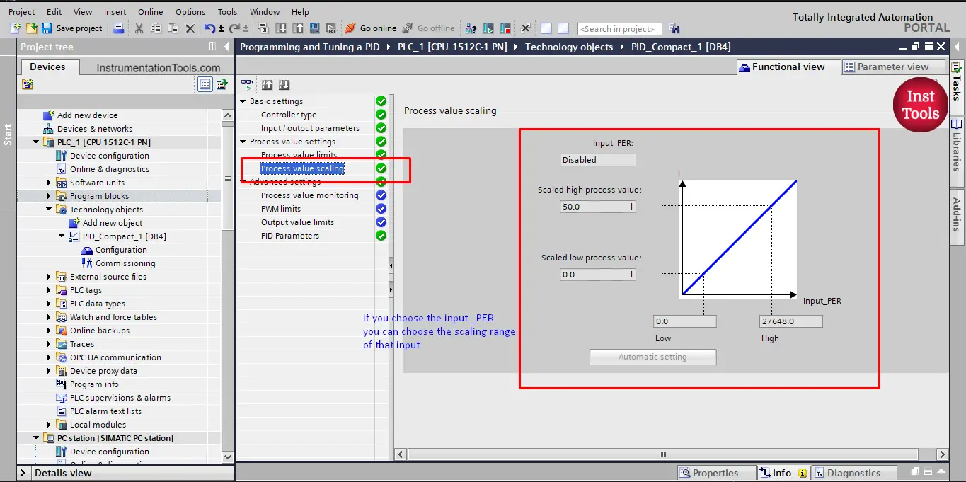
Picture 8. Process value scaling.
If you use the Input_PER, then as you see from the previous picture you can set your process value limit with respect to the 0-27648 scaling you have.
If you want to set up a warning when your process value hit a low or a high limit, then you can configure that in the process value monitoring tab. See picture 9.
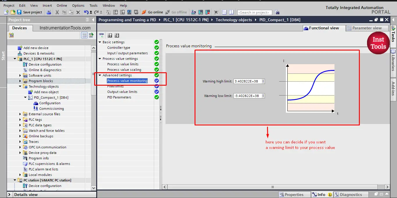
Picture 9. Process value monitoring.
Next in the setting list you will find the PWM limits, see picture 10.
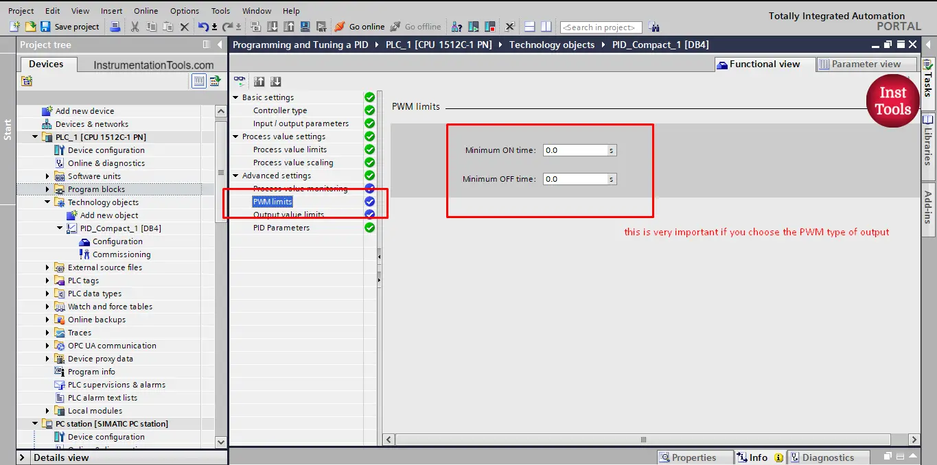
Picture 10. PWM limits
in here you can set the minimum ON and OFF time of your output, imagine you have a pump or a valve in your system that the PID is controlling through a PWM output, you don’t want the PID to just give your pump a train of a very fast based ON/OFF behavior because that will probably cause your pump to burn out. So you can tell the PID from this setting to turn the pump on for a minimum time before closing it and vice versa.
You can have the same control with your PID if you don’t have PWM output from the next setting, the output value limits. See picture 11.
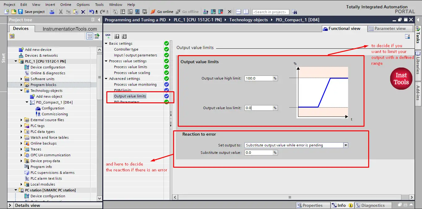
Picture 11. Output value limits.
You can control the low and high limits of your control output, for example, you can make the low limit 20% and that will make the PID run the pump for at least 20% of its flow. So your control range will be from 20% to 100%.
Finally and most importantly, you can set your PID parameters in the configuration mode from the next tab, the PID parameters tab, see picture 12.
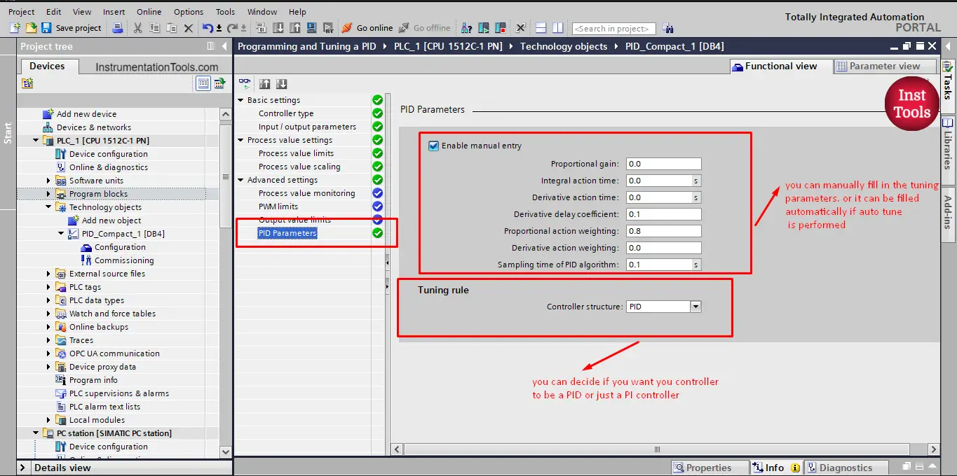
Picture 12. PID parameters.
Here you can write the tuning parameters for your PID gains P, I, and D in case you know them or in case you made the tuning yourself and you have the parameters from elsewhere. You can also choose to decide to use a PID or just a PI controller.
If you don’t have these parameters, you can upload them automatically after you make tuning to your PID.
How to Perform Tuning of the PID?
Now that you finished your PID configuration, you can tune your controller just as easily from the commissioning tab in the project tree. See picture 13.
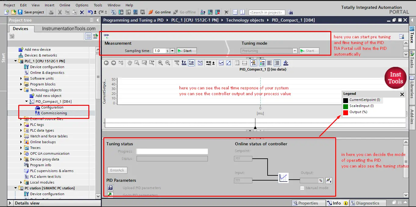
Picture 13. Commissioning your PID
On the commissioning page, you have your screen divided into 3 parts, the upper page is where you can start pre-tuning and fine-tuning the PID.
In the middle, you will have a graph area to show you the real-time response of your system. You can see the controller output and the process value. And each time the set point changes, you will see the behavior of your PID to catch this new set point. Even if the set point didn’t change but for example the demand from our tank supply is increased, you will see the PID reaction to supply that demand and also keep the set point at its required value.
In the third area, you will have the online status of your controller and you can also decide the operating mode of your PID. See the following simulation video showing the auto-tuning procedure of the PID in the TIA Portal.
From the video, you can see that after pre-tuning is done, our PID found the P, I, and D parameters to best suit our system. You can see that when the set point or the outflow changes the controller will react very quickly to bring the set point back to the required values.
You can now upload your tuning parameters directly into your project with a simple button click, see picture 14.
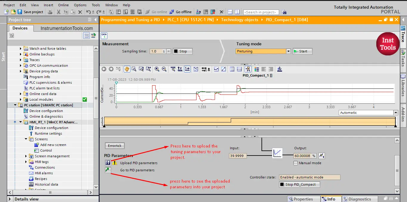
Picture 14. Upload your parameters.
Once you have uploaded your parameters, you can find them in the PID parameters tab in the configuration view. See picture 15.
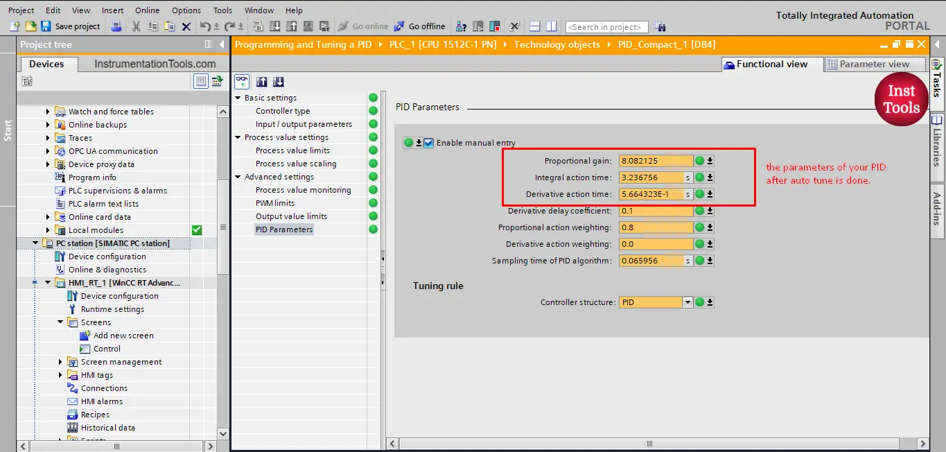
Picture 15. PID parameters.
The next step should be to perform a fine-tuning procedure to the PID from the same commissioning view, however, because we don’t have a real system and we are just simulating the behavior of the tank and pump using mathematical calculations we can’t do the fine-tuning step.
When you have a real system you can make the fine-tuning where your PID will try to find the parameters that will give the system a better response and even eliminate the overshoot of your process value and directly reach the set point.
In the future, if we have a real system, we can show what it looks like.
What are the different Tuning Methods of PID Controller?
You don’t have to make the tuning of your PID using TIA Portal; there are many different methods that try to find the best PID parameters for your system. It is mostly mathematical methods based on trial and error. I would recommend using the auto-tune feature in TIA Portal.
But here are some of the methods used to achieve the same parameters.
- Heuristic tuning.
- Ziegler-Nichols tuning method
- Cohen-Coon tuning method
- Kappa-Tau tuning method
- Lambda tuning method
- And a few others.
Download: Tuning PID
Conclusion
- Use a cyclic interrupt with your PIDs.
- Configure your PID to best suit your system.
- The auto-tune feature in TIA Portal is very useful and effective.
If you liked this article, then please subscribe to our YouTube Channel for Instrumentation, Electrical, PLC, and SCADA video tutorials.
You can also follow us on Facebook and Twitter to receive daily updates.
Read Next:
- Motor Faceplate in Graphics
- HMI and VFD Control System
- Update PLC Firmware Version
- PLC ON-OFF Control with Hysteresis
- Design Counters in PLC Program


Why the Inst-Tool doesn’t have a “Download” Icon for me to download each article?