Counters are a very important instruction in PLC programming. You require it in almost every logic. Be it counting something to counting events, counters form an important part of PLC programming.
Because event count is used in many applications and it helps PLC programmers save time in writing cumbersome coding. But, many times, it is always required to find a backup solution for a plan if it does not work.
In the case of counters too, a PLC programmer must know a backup logic if it does not work properly. For that, two instructions can be combined and written – move and addition.
In this post, we will learn how to design counters in PLC programming with a move and add instruction.
Counters
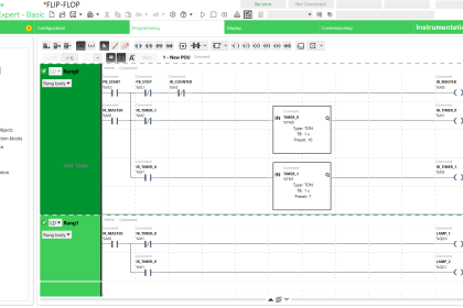
First of all, we will see a counter instruction on how it is written. Refer to the below image. As you can see, a counter has three inputs – count, reset, and set value; and has two outputs – done and current value.
A count input is required to provide the counter with a pulse for counting it, a reset input is required to reset the counter, and a set value is required for feeding the counter with set counts. A done output is used to denote that the counter has finished counting and the current value shows the present value of counts that the counter has counted till now.
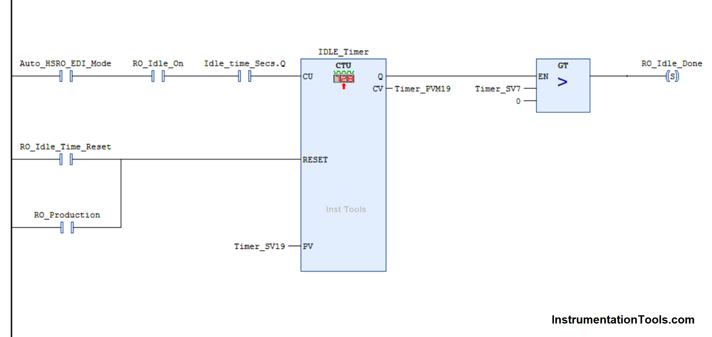
When count input is received, the counter increments by a value. The count input works on a pulse basis and not on a continuous basis. When the counter reaches its set count, then the output done bit goes on.
The only way to then turn it off is by giving the reset input. The count value will become zero on this input and the counter resets due to this. It is to be noted that even if the count has been reached and you still give count input, then too the count will go on incrementing.
You can also see that a comparison block is used after counter output, which allows it to pass to the final bit to be turned on. This prevents the final bit from turning on unnecessarily if the set count is zero.
Design Counters in PLC With a Move Instruction
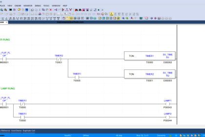
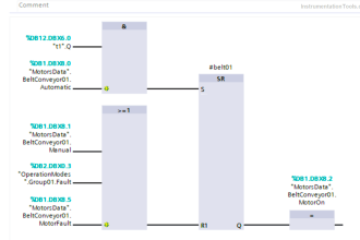
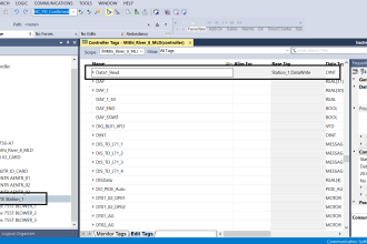
Now, we will see how to write this same coding with the help of move and add instructions. Refer to the below image. In the first rung, the count input is replaced with an add instruction.
The addition will happen if the input condition is true, and that too with a pulse. Pulse must be used, otherwise, continuous addition will go on and there will be no control over it.
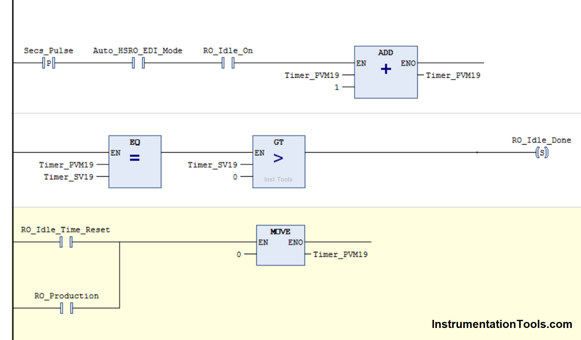
In the second rung, it compares whether the set counts have been reached or not. It also checks whether the set count is more than zero or not. If these conditions are true, then the output turns on.
In the third rung, the counter value becomes zero on the receipt of the corresponding inputs. This equals the operation of reset input.
These three rungs are enough to replicate the function of a counter. You can use either a counter or this PLC logic, according to your needs. But, it is to be noted that we can program a counter by writing this way too.
In this way, we saw how to write counters in PLC programming with a move and add instruction.
If you liked this article, then please subscribe to our YouTube Channel for Instrumentation, Electrical, PLC, and SCADA video tutorials.
You can also follow us on Facebook and Twitter to receive daily updates.
Read Next:
- Omron PLC Online Training Course
- Difference Between PNP and NPN Sensor
- Light Tower in Industrial Automation
- Batch Simulator PLC Example Program
- PLC Program for Stage Control Project


More products information