In this article, you will learn the warning light system and the PLC programming solution for the machine indicator lights.
Note: These PLC problems offer an opportunity for the students to practice the programs.
Machine Indicator Lights
Problem Statement:
Design a PLC ladder logic for the following application.
We are using one Push Button to control Machine 1, Machine 2, Red Light 1, Red Light 2, Green Light 1, and Green Light 2.
Suppose you have a warning Light system to indicate whether a Machine is running or not.
Two Red Lights will indicate individual Machine 1 and Machine 2 running status. These machines operate for 10 seconds and 20 seconds respectively.
Two Green Lights will indicate when machines are not operating.
PLC Programming Solution
Instrumentation Tools provides free PLC programming solutions for industrial examples.
This PLC logic video explains the indicator lights program.
Inputs and Outputs
Digital Inputs:
Start Button: I0.0
Digital Outputs:
Machine 1: Q0.0
Machine 2: Q0.1
Red Light 1: Q0.2
Red Light 2: Q0.3
Green Light 1: Q0.4
Green Light 2: Q0.5
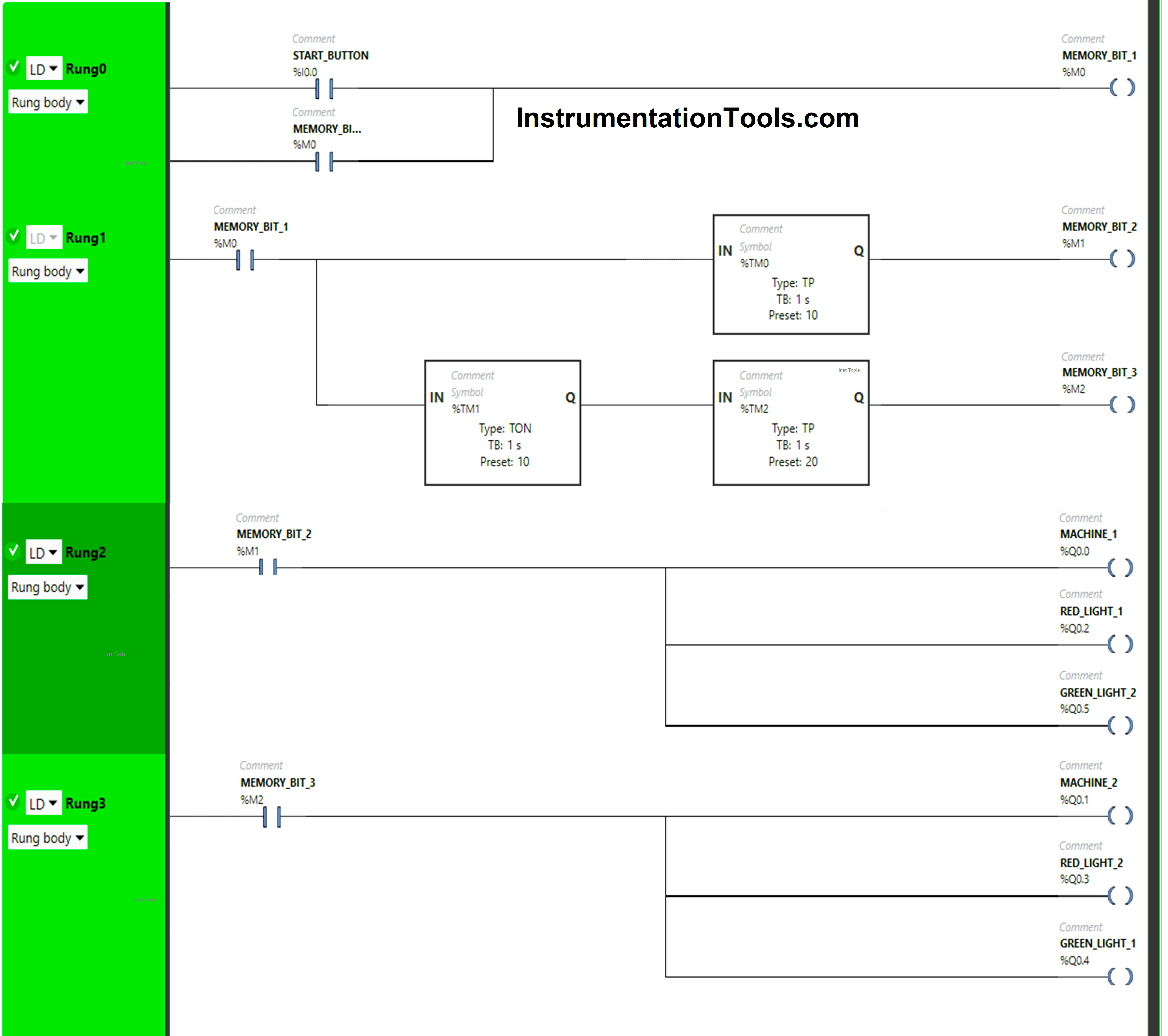
PLC Ladder Logic
Program Description
We have used Normally Open Contacts for Start Button(I0.0) and Memory Bits.
In Rung 0:
- Normally Open Contact is used for the Start Button(I0.0) to Turn ON Memory Bit 1 (M0).
- Memory Bit 1 (M0) is latched so that when the Start Button(I0.0) turns OFF, Memory Bit 1 (M0) still remains ON.
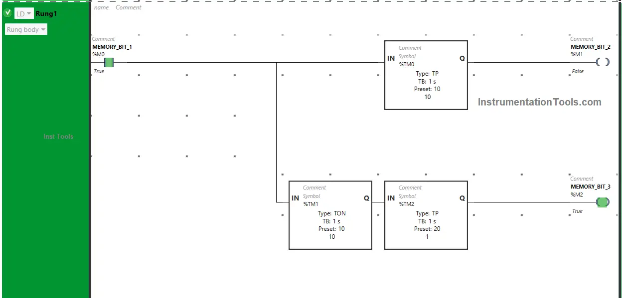
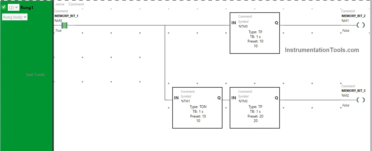
In Rung 1:
- Normally Open Contact is used for Memory Bit 1 (M0) to Turn ON Memory Bit 2 (M1) and Memory Bit 3 (M2).
- Timer-type TP is used to Turn ON Memory Bit 2 (M1) for a limited time.
- Time-type TON is used to delay the turning ON time of Memory Bit 3 (M2) for some time.
- Timer-type TP is used to Turn ON Memory Bit 3 (M2) for a limited time.
In Rung 2:
- Normally Open Contact is used for Memory Bit 2 (M1) to Turn ON the outputs Machine 1 (Q0.0), Red Light 1 (Q0.2), and Green Light 2 (Q0.5).
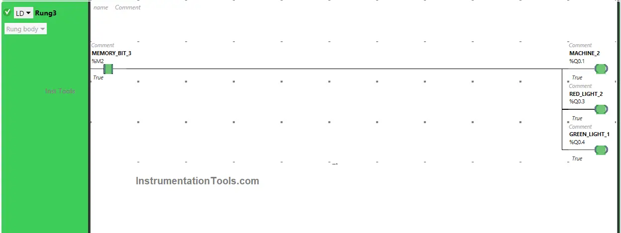
In Rung 3:
- Normally Open Contact is used for Memory Bit 3 (M2) to Turn ON the outputs Machine 2 (Q0.1), Red Light 2 (Q0.3), and Green Light 1 (Q0.4).
Simulation Results
Now we simulate the PLC program and analyze the results. Please note that we may show the partial logic code instead of the complete program.
When the Start Button (I0.0) is pressed and released, Memory Bit 1 (M0) turns ON and stores the data that the Start Button (I0.0) is pressed as Memory bits store the data.
Memory Bit 1 (M0) is latched so that when the Start Button (I0.0) is released, Memory Bit 1 (M0) still remains ON.
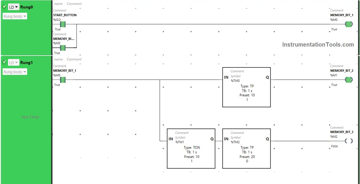
When Memory Bit 1 (M0) turns ON in Rung0, Normally Open Contact used for Memory Bit 1 (M0) in Rung1 will be in True State and will pass the signal to turn ON Memory Bit 2 (M1) and Memory Bit 3 (M2).
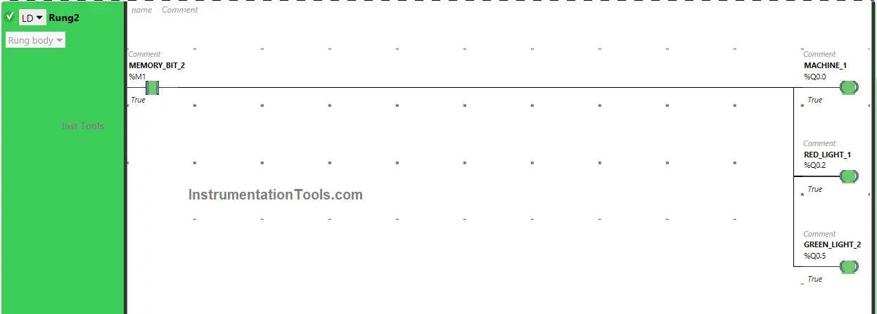
When Memory Bit 2 (M1) turns ON in Rung1, Normally Open Contact used for Memory Bit 2 (M1) will be in True state and pass the signal to turn ON the outputs Machine 1 (Q0.0), Red Light 1 (Q0.2) {which indicates Machine 1 (Q0.0) is ON} and Green Light 2 (Q0.5) {which indicates Machine 2 (Q0.1) is OFF}.
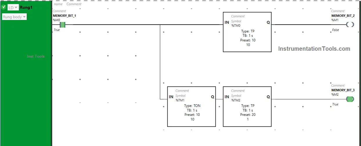
In Rung1, Memory Bit 2 (M1) turns OFF after some time as Timer Function Block type TP is used to turn ON Memory Bit 2 (M1) for a limited time.
The time is set to 10 seconds.
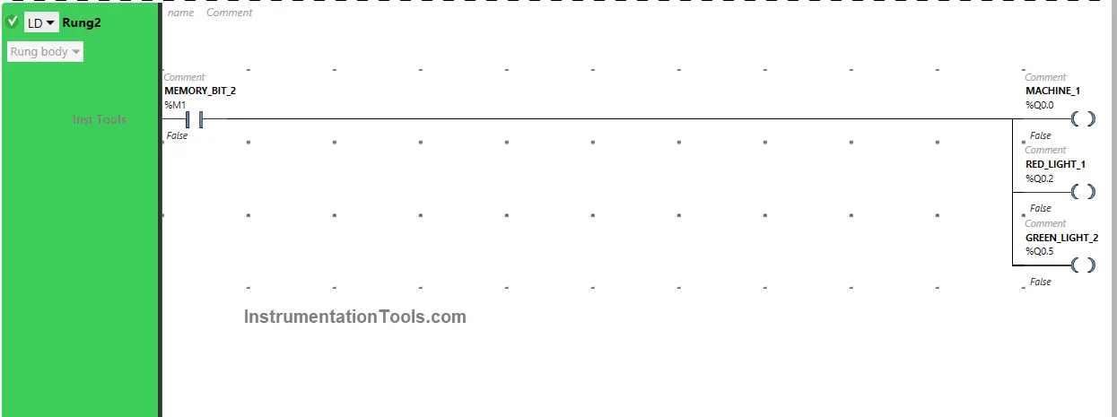
After 10 seconds, Memory Bit 2 (M1) turns OFF. When Memory Bit 2 (M1) turns OFF in Rung1.
Normally Open Contact used for Memory Bit 2 (M1) will be in a false state and does not allow the signal to pass through it and the outputs Machine 1 (Q0.0), Red Light 1 (Q0.2), and Green Light 2 (Q0.5) will turn OFF.
When Memory Bit 1 (M0) turns ON in Rung1, Memory Bit 3 (M2) will turn ON after 10 seconds (i.e immediately after Memory Bit 2 (M1) turns OFF) as Timer Function Block type TON is used to delay the turning ON time of Memory Bit 3 (M2).
The time is set to 10 seconds.
After 10 seconds, Memory Bit 3 (M2) will turn ON. When Memory Bit 3 (M2) turns ON in Rung1.
Normally Open Contact used for Memory Bit 3 (M2) will be in True state and pass the signal to turn ON the outputs Machine 2 (Q0.1), Red Light 2 (Q0.3) {which indicates Machine 2 (Q0.1) is ON} and Green Light 1 (Q0.4) {which indicates Machine 1 (Q0.0) is OFF}.
In Rung1, Memory Bit 3 (M2) turns OFF after some time as Timer Function Block type TP is used to turn ON Memory Bit 3 (M2) for a limited time.
The time is set to 20 seconds. After 20 seconds, Memory Bit 3 (M2) turns OFF.
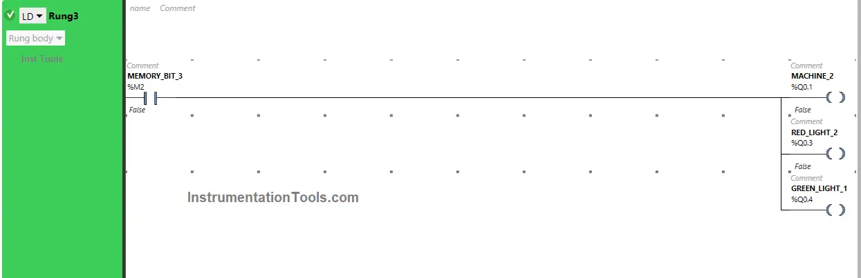
When Memory Bit 3 (M2) turns OFF in Rung1, Normally Open Contact used for Memory Bit 3 (M2) will be in a false state and does not allow the signal to pass through it and the outputs Machine 2 (Q0.1), Red Light 2 (Q0.3) and Green Light 1 (Q0.4) will turn OFF.
If you liked this article, please subscribe to our YouTube Channel for PLC and SCADA video tutorials.
You can also follow us on Facebook and Twitter to receive daily updates.
Read Next:
- Alarm Indication in Process Control Ladder Logic
- Automatic Car Washing using PLC Programming
- Light Tower Industrial Automation Programming
- Modbus Communication Questions and Answers
- Three Motors control PLC Programming Logic