Inst ToolsInst ToolsInst Tools
  • Courses
  • Automation
    • PLC
    • Control System
    • Safety System
    • Communication
    • Fire & Gas System
  • Instrumentation
    • Design
    • Pressure
    • Temperature
    • Flow
    • Level
    • Vibration
    • Analyzer
    • Control Valve
    • Switch
    • Calibration
    • Erection & Commissioning
  • Interview
    • Instrumentation
    • Electrical
    • Electronics
    • Practical
  • Q&A
    • Instrumentation
    • Control System
    • Electrical
    • Electronics
    • Analog Electronics
    • Digital Electronics
    • Power Electronics
    • Microprocessor
  • Request
Search
  • Books
  • Software
  • Projects
  • Process
  • Tools
  • Basics
  • Formula
  • Power Plant
  • Root Cause Analysis
  • Electrical Basics
  • Animation
  • Standards
  • 4-20 mA Course
  • Siemens PLC Course
Reading: Functional Block Diagram in PLC for Oil and Water Process
Share
Font ResizerAa
Inst ToolsInst Tools
Font ResizerAa
  • Courses
  • Design
  • PLC
  • Interview
  • Control System
Search
  • Courses
  • Automation
    • PLC
    • Control System
    • Safety System
    • Communication
    • Fire & Gas System
  • Instrumentation
    • Design
    • Pressure
    • Temperature
    • Flow
    • Level
    • Vibration
    • Analyzer
    • Control Valve
    • Switch
    • Calibration
    • Erection & Commissioning
  • Interview
    • Instrumentation
    • Electrical
    • Electronics
    • Practical
  • Q&A
    • Instrumentation
    • Control System
    • Electrical
    • Electronics
    • Analog Electronics
    • Digital Electronics
    • Power Electronics
    • Microprocessor
  • Request
Follow US
All rights reserved. Reproduction in whole or in part without written permission is prohibited.
Inst Tools > Blog > PLC Tutorials > Functional Block Diagram in PLC for Oil and Water Process

Functional Block Diagram in PLC for Oil and Water Process

In this post, we will see a case scenario of writing a PLC program for separating oil and water process using functional block diagram.

Last updated: September 13, 2024 1:30 pm
Viral Nagda
PLC Tutorials
No Comments
Share
6 Min Read
SHARE

Functional block diagram language is preferred in PLC programming for its efficient troubleshooting and ease of writing. It is best suitable for many large-scale and complex applications.

Contents
PLC for Oil and Water ProcessFunctional Block Diagram in PLC

PLC for Oil and Water Process

Let us see one application of separating oil and water in a tank. This is a process application and can be written and viewed easily in a functional block diagram. In this post, we will see a case scenario of writing a PLC program for separating oil and water using a functional block diagram.

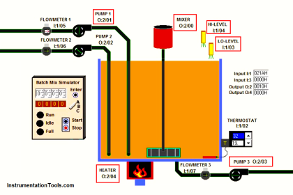
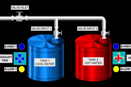
Let us understand the process first. Refer to the below image. It consists of a tank with the following components – tank filling valve, heater, level sensor, temperature sensor, water valve, oil valve and diverter valve.

Plc Program for Oil and Water Separation Process

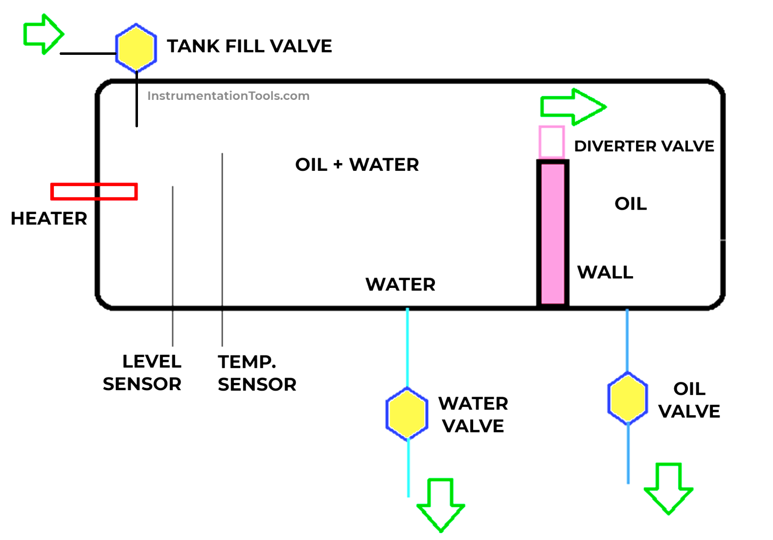
The process starts with a tank fill valve. This valve opens to fill the mixture of oil and water first. It fills until a certain level of 50 liters is reached. Once reached, the heater starts to heat the mixture. As it is heating, the oil starts to separate from the water after a certain period of time, and the water starts to settle down in the bottom of the tank.

Once the temperature of 100 degrees is reached, the heater stops. After that, the diverter wall mounted on the wall opens to move downwards. This starts to spill the oil present on the upper layer in the other part of the wall. This goes on till the valve-on-timer.

Once the timer is done, the output goes off and it starts to move up automatically, as it is a single-acting valve. As soon as the valve starts to move up, the drain valves of water and oil open and remain on for a certain time. After this time, the logic resets and starts again from the filling cycle.

Functional Block Diagram in PLC

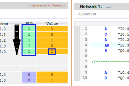
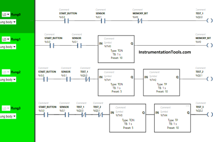
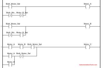
Now that we have seen the case, let us see the program written for the same. Refer to the below image.

We will require the following PLC IO’s:-

  • 5 digital outputs (tank filling valve, heater, water valve, oil valve, and diverter valve),
  • 2 analog inputs (level sensor and temperature sensor).
Functional Block Diagram in PLC for Oil and Water Process

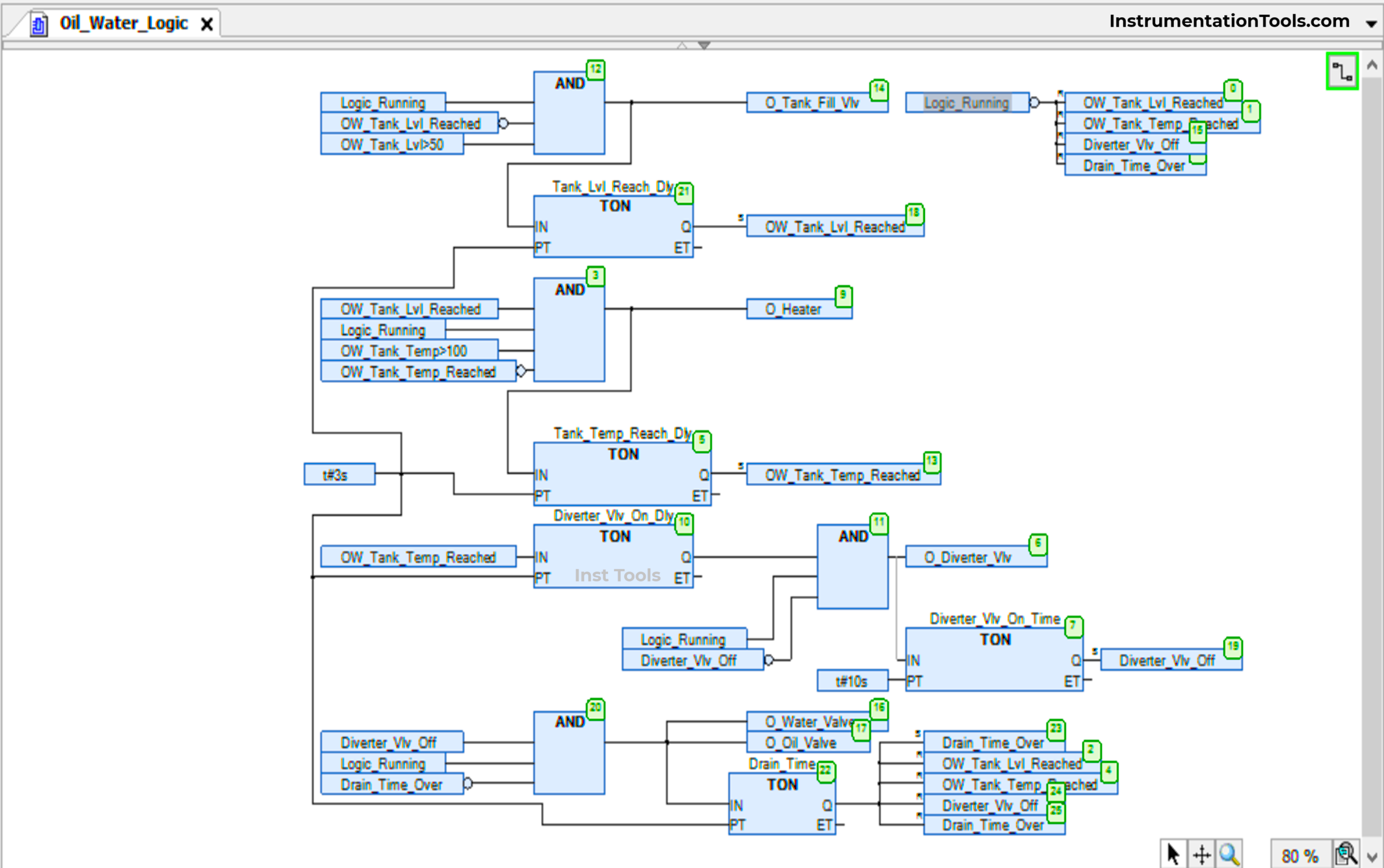
As we see the logic, we first start the filling cycle from the top of the logic by turning the fill valve on. For that, we use an AND block comprising a logic running bit, tank level reached negate bit, and a condition checking tank level for more than 50 liters.

The logic running bit is assumed here to be coming from some other part of logic and is the master one. When the level is reached, the bit tank level reached is set and this cuts-off the fill valve. (Note that the level is checked after a delay of 3 seconds, to avoid any fluctuations.)

As soon as the level is reached, the heater starts to heat the tank. For that, we use an AND block comprising a logic running bit, tank temperature reached negate bit, tank level reached bit, and a condition checking tank temperature for more than 100 degrees. When the temperature is reached, the bit tank temperature reached is set and this cuts-off the heater. (Note that the temperature is checked after a delay of 3 seconds, to avoid any fluctuations.)

As soon as the temperature is reached, the diverter valve starts to empty the tank by spilling the upper layer of oil separated after heating. For that, we use an AND block comprising a logic running bit, diverter valve off negate bit and diverter valve on delay timer done bit. When the on-time is reached, the bit diverter valve off is set and this cuts-off the diverter valve. As soon as the valve supply goes off, it starts to move upwards automatically and comes back to it’s original position.

As soon as the diverter valve goes off, the drain timer starts to throw the oil and water out of the tank by opening the water and oil valves. For that, we use an AND block comprising a logic running bit, diverter valve off  bit and drain timer over negate bit. When the on-time is reached, the bit drain timer over is set and this cuts-off the oil valve and water valve. Immediately following it, all the bits are reset as seen in the image and the logic restarts once again.

In this way, we saw the PLC program for oil and water separation process using a functional block diagram.

Read Next:

  • Inside the PLC Control Panel: Test Quiz
  • AI, AO, DI, DO Questions (PLC I/O Types)
  • Codesys Timer ON, Timer OFF, Pulse Timer
  • Mixing Program with Timers and Counters
  • Oven Control Application with PLC Control
Don't Miss Our Updates
Be the first to get exclusive content straight to your email.
We promise not to spam you. You can unsubscribe at any time.
Invalid email address
You've successfully subscribed !

Continue Reading

Download a Ladder logic program to GE PLC
Turbine-Compressor System Architecture
Types of Allen Bradley PLC
Playground Swing Logic Exercise Program in PLC
PLC Packing Machine Control System Program in XG5000
Difference between Machine Expert Basic and Machine Expert – Schneider PLC
Share This Article
Facebook Whatsapp Whatsapp LinkedIn Copy Link
Share
Leave a Comment

Leave a Reply Cancel reply

Your email address will not be published. Required fields are marked *

Stay Connected

128.3kFollowersLike
69.1kFollowersFollow
210kSubscribersSubscribe
38kFollowersFollow

Categories

Explore More

PLC FBD Programming for Burglar Alarm Security System
PLC Program for Controlling Sequence of Conveyors with Interlock
Schneider PLC Example: Control Lamps Sequences
What is a Tower Lamp? – Light Tower in Industrial Automation
Pump and Mixer Operations Example: PLC Timer-Based Control
PLC Programming using Level Switches
D Flip Flop PLC Ladder Logic
Workstation Healthiness Checks

Keep Learning

What is Siemens TDC - Siemens Control System

What is Siemens TDC? – Siemens Control System

How Could FB and FC Make Me Professional PLC Programmer

How Could FB and FC Make Me Professional PLC Programmer?

Sorting Defective Parts PLC Logic

Advanced PLC Programming for Defective Parts Sorting

Step-by-step import export in FactoryTalk View

FactoryTalk View Studio – Import and Export Tutorial

How is Data Stored in Standard Modbus Protocol?

How is Data Stored in Standard Modbus Protocol?

PLC Karnaugh maps

How to Simplify PLC Coding Using Karnaugh Maps?

Difference between Motion Controller and PLC

Difference between Motion Controller and PLC

PLC Automatic Pedal Switch for Speed Control

PLC Automatic Pedal Switch for Speed Control

Learn More

Ball Valve root cause

Ammonia Feed Ball Valve to Ship Tank Closed

Yokogawa DCS

Yokogawa DCS and SIS System Architecture

Brix Measurement

Measurement of POL, pH, and BRIX in the Sugar Industry

ISA symbols for Process Instrumentation

ISA Codes & Symbols for Process Instrumentation

Multiphase Flow Meter Calibration Procedure

Multiphase Flow Meter Calibration Procedure

Control Valves Classification

Classification of Control Valves

Valve Actuator Passing

Lessons Learned from Actuator Passing Incidents

Cable Trays

Types of Cable Trays – Purpose, Advantages, Disadvantages

Menu

  • About
  • Privacy Policy
  • Copyright

Quick Links

  • Learn PLC
  • Helping Hand
  • Part Time Job

YouTube Subscribe

Follow US
All rights reserved. Reproduction in whole or in part without written permission is prohibited.
Welcome Back!

Sign in to your account

Username or Email Address
Password

Lost your password?