In this article, a simple example will teach you the conversion from Boolean algebra to PLC logic.
Note: The PLC logic shown here is for educational use only for students and technicians to learn the basics.
Boolean Algebra to PLC Logic
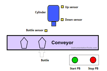
Problem Statement
Design a PLC ladder logic for the following Boolean Expression.
We are using toggle Inputs to control the output.
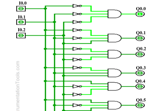
Y = (A+B) (C+D)
Video
Watch the video to learn this PLC program example.
Digital Inputs
The inputs listed below.
A: I0.0
B: I0.1
C: I0.2
D: I0.3
Digital Outputs
The outputs listed below.
Y: Q0.0
PLC Programming
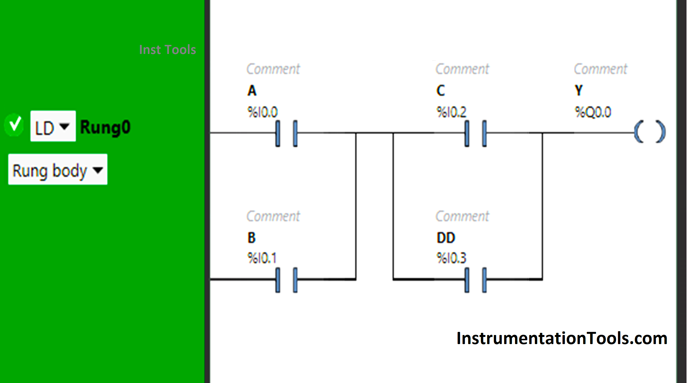
Find the equivalent plc program for the given Boolean expression.
PLC Program Description
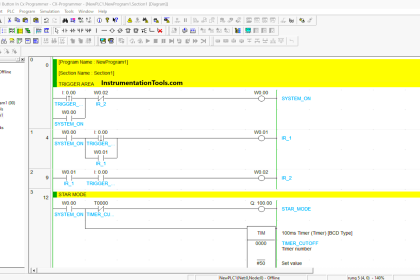
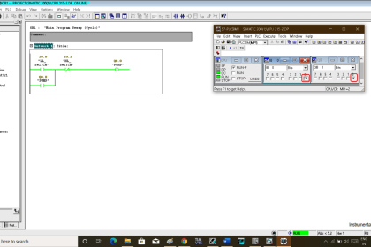
- In this program, we used Schneider Electric PLC software. You can use any brand of PLC software.
- In the above PLC program, Normally Open Contacts are used for input A, input B, input C, and input D.
- Input A and Input B are connected in parallel, thus implementing OR Logic Gate.
- There is again the implementation of OR Logic Gate as Input C and Input D are connected in parallel.
- There is also implementation of AND Logic Gate as A+B is connected in series with C+D.
- For the output Y (Q0.0) to be ON, either Input A or Input B should be ON and either Input C or Input D should be ON.
- If input A and input C are ON or If input A and input D are ON or If input B and input C are ON or input B and input D are ON, then the output Y (Q0.0) will be ON.
Test Results
Now check the PLC program simulation results.
When Input A and Input C are ON
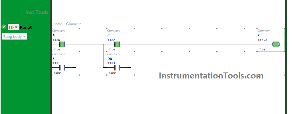
When Input A and Input C are turned ON, the output Y (Q0.0) will turn ON. The inputs are taken as Normally Open Contacts and when in true state, the signal will pass through these contacts.
As a result, the output Y (Q0.0) will turn ON. If only one input is turned ON i.e., either input A or input C is turned ON, then the output Y Q(0.0) will not turn ON.
When Input A and Input D are ON
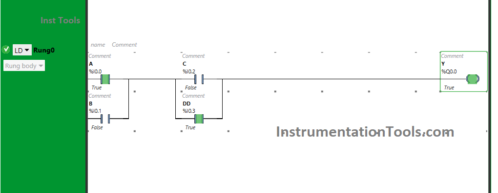
Y (Q0.0) will turn ON when Input A and Input D are turned ON. These inputs are used as Normally Open Contacts and when in true states, the signal will flow through these contacts which results in turning ON the output Y (Q0.0).
For the output Y (Q0.0) to turn ON, both the inputs should be ON. If only one input i.e., if input A or Input D is turned ON, then the output Y (Q0.0) will not turn ON.
When Input B and Input C are ON
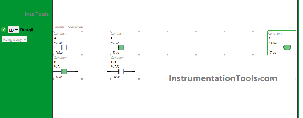
The signal will flow through Input B and Input C as these inputs are taken as Normally Open Contacts. When the input B and input C are in true state, the output Y (Q0.0) will turn ON.
So, both the inputs i.e., input B and input C should be ON and then only the output Y (Q0.0) will turn ON. Turning ON only one input will not turn ON the output Y (Q0.0).
When Input B and Input D are ON

As Normally Open Contacts used for Input A and Input B are in the true state, the signal will pass through these two Inputs and Y(Q0.0) will turn ON.
The output Y (Q0.0) will turn ON only if both these inputs are turned ON otherwise it will remain OFF.
If you liked this article, please subscribe to our YouTube Channel for PLC and SCADA video tutorials.
You can also follow us on Facebook and Twitter to receive daily updates.
Read Next:
- Basic PLC Alarm Programming Example
- Project System Architecture Documents
- Boolean Logic to PLC Programming
- Compare CompactLogix and ControlLogix
- Standard 4 to 20 mA Conversion Formula