Root Cause Analysis (RCA): Within Few Weeks Failing Weigh Feeders Mechanical Variable Speed Drives (VSD).
Note: This is a real scenario that happened way back in the olden days during pneumatic transmitters times. With the advancement of technologies now we have smart transmitters and advanced VFD drives in industrial plants.
These articles will help you to improve your troubleshooting skills and knowledge.
Weigh Feeder Salient Information
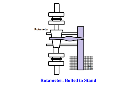
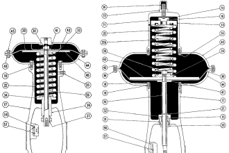
Weigh Feeders are short conveyor belts. 2.5 kW 1480 RPM 400 V 50 Hz motor drives the conveyor belt at low speeds via a Mechanical Variable-speed Drive (MVSD; fig 1).
A load cell below the belt outputs 3-15 psi pneumatic signals proportional to the kg/m belt loading. Flanged to MVSD casing speed transmitter outputs pneumatic signal proportional the output shaft RPM i.e., the belt speed m/H.
Housed in a nearby box an analog computer outputs (kg/m)*(m/H) = kg/H pneumatic signal.
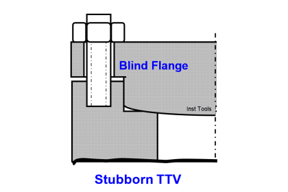
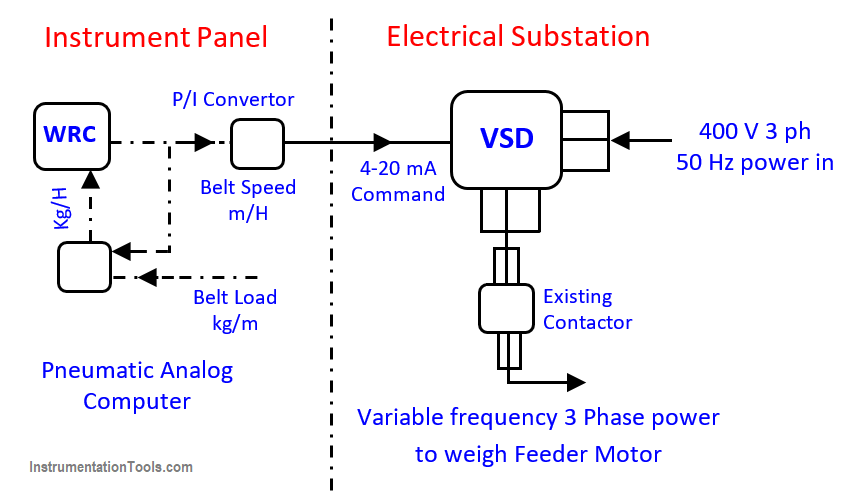
The panel mounted Weight Recording Controller (WRC; fig 2) controls the feed rate at set point by commanding an actuator that pulls / pushes the MVSD’s a lever to change the weigh feeder belt speed.
Weigh Feeder Problem
The dusty and harsh environs located MVSD and the pneumatic RPM transmitter of many moving and sliding parts rotating at RPMs as high as 2000 failed too often.
Repairing these delicate items was mostly unsatisfactory; hence, both failed repeatedly within weeks. Even the too expensive and long delivery vendor spare parts lives were poor; consequent local substitutions even poorer!
Thus, the 9 Nos. weigh feeder availabilities were 70-80% only and reduced NPK production 10-15%.
Author Solution
A visiting sales person demonstrated Frequency Converter aka electronic variable speed drive abbreviated (VSD), so impressed the author that he instantly recognized it as ‘dream became true’ MVSD replacer and the 3 yearlong problems solver.
Hence, he retained the demonstration model ignoring the sale engineer protests and requested the purchase officer to give him a purchase order and the finance department to pay him immediately.
Figs 1 & 2, the author’s scheme shows how the low cost indigenous highly reliable VSD and another bought out item, the P/I converter replaced the MVSDs and pneumatic speed transmitters – both imported and pain in the neck very high cost items.
The P/I converter converts the standard 3-15 psi pneumatic instrument signals into standard 4-20 mA instrument current signals.
More on Variable Speed Drive (VSD)
The VSD, a 1980s debuted solid state electronic device converts the standard 400 V 50 Hz 3 phase power into set e.g. 0 to 80 Hz frequency adjustable 3-phase power proportional to standard 4 to 20 mA control current signal.
Most VSD’s offer constant V/f relationship; this way the motor output shaft torque is constant at all RPMs. However, the VSD output volt saturates to supply volt at frequencies above the supply frequency.
Table 1 below shows a VSD powered 4-pole induction motor RPM for 4 20 mA signals:
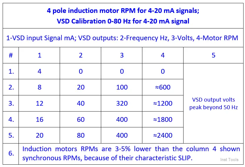
The column with label number 1 shows the 4mA, 8mA, 12mA, 16mA, and 20 mA current signals.
The column with label number 2 shows the frequency in steps of 0Hz, 20Hz, 40Hz, 60Hz, and 80 Hz.
The column with label number 3 shows the voltage in steps of 0 volts, 100 V, 320 V, 400V.
The column with label number 4 shows the motor speed in steps of 0,, 600, 1200, 1800, and 2400 rpm.
VSD Installation, Wiring and Tubing
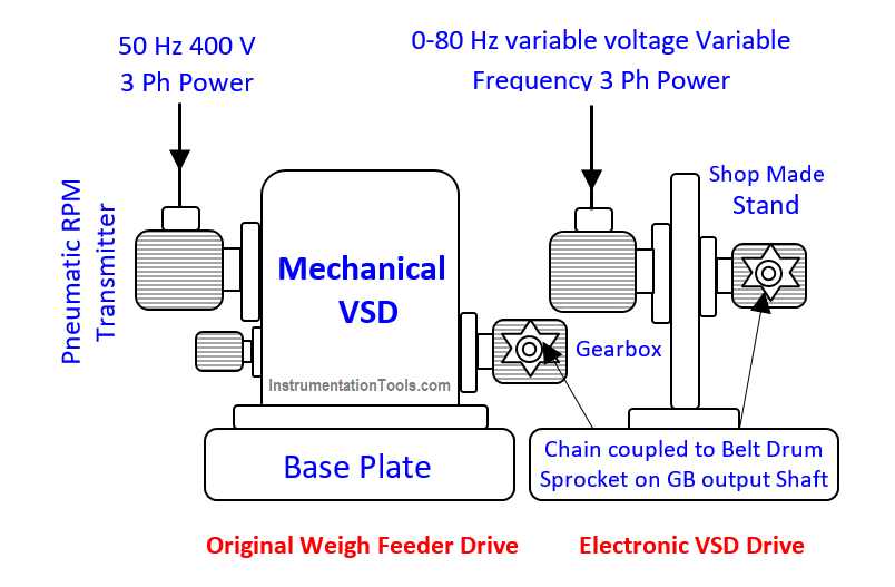
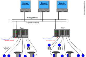
A mechanical, electrical and instrument crew team fitted a spare flanged motor and GB to a shop made stand (fig 1), coupled them as before, fixed the VSD in the substation, fixed a spare analog computer and P/I converter at instrument panel back and laid the necessary wiring and tubing without plant shutdown (SD).
During a fortnightly 4 hour housekeeping SD, the team bolted the stand to the base-plate, terminated the tube and cable connections, completed all necessary tasks according to figs 1 & 2 and switched on the VSD driven weigh feeder successfully.
A week after the first feeder successful run, the author confirmed the order for balance items for other weigh feeders and one spare set. Within a week of their arrival the team commissioned all VSD driven weigh feeders.
How the VSD eliminates the Pneumatic Speed transmitter besides the MVSD?
The VSD eliminates the Pneumatic Speed transmitter besides the MVSD thus: The motor speed and hence belt speed is proportional to the frequency i.e. to the VSD input signal current, which is proportional to WRC pneumatic output.
The newly bought P/I convertor renders the WRC 3-15 psi signals into proportional 4-20 mA standard instrument current signals, which only the VSD accepts. Hence WRC pneumatic output signal is proportional to belt speed.
Hence, the author got WRC output pneumatic signal T-connected as belt speed signal to the pneumatic analog computer.
The analog computer receives belt load signal as before. Hence it outputs kg/H raw materials’ feed rate to WRC as before.
Thus, the VSD not only eliminates the MVSD but also the speed transmitter – both terrible plant availability reducers!
Weigh Feeders VSD Drives Benefits
Weigh Feeders New Drives’ Benefits are:
- Gone are the most failure prone MVSD and ST, their associated maintenance efforts, long down-times and poor plant availabilities
- Re-locating the field installed pneumatic analog computer and locating the new P/I converter at instrument panel back and the VSD in the substation (fig 2) – both clean areas – eliminate new VSD system likely problems and increase its reliability even more
- Thanks to this and many other modifications weigh feeders availabilities touched 100% and the plant produced higher than rated capacities. This is a practical ‘design out maintenance’ example
- Weigh feeder drive and other maintenance costs became negligible
- The VSD and P/I converters paid for themselves in less than a day! Often replaced MVSDs each cost $ 3000, STs $ 1800 – 80s figures. On the other hand each never replaced VSD costs Rs 25000 and P/I converter Rs 1500 only. Revenue from higher than rated production a handsome bonus!
Author: S. Raghava Chari
Do you face any similar issues? Share with us through the below comments section.
If you liked this article, then please subscribe to our YouTube Channel for Instrumentation, Electrical, PLC, and SCADA video tutorials.
You can also follow us on Facebook and Twitter to receive daily updates.
Read Next: